
Ball-shaped object screening device for package field

A screening device, spherical technology, applied in the field of screening, can solve the problems of high cost, low installation efficiency, inconvenient installation of the structure with the size of the screening ball, etc., and achieve the effect of reducing installation cost and high utilization rate

Active Publication Date: 2019-11-08
平邑经发产业发展有限公司
View PDF5 Cites 0 Cited by
  • Summary
  • Abstract
  • Description
  • Claims
  • Application Information

AI Technical Summary

Problems solved by technology

[0004] At present, there is a sorting mechanism, as recorded in Chapter 14 of "Practical Mechanisms and Devices Atlas of Mechanical Design", when spherical objects come down from the hopper, they must pass through a door, which is also the spring lock of the swing door; it meets the standard size The ball will pass directly without touching the gate, but the gate is generally designed on the upper side of the pipe, and the lower side of the pipe is designed with a swing plate. When the oversized ball hits the gate on the upper side, the upper The door will control the swing of the swing plate on the lower side through the transmission, so that the balls exceeding the standard size will fall into the groove specially equipped with waste products. It will bring inconvenience to the installation of the structure with the size of the screening ball, and it is not easy to arrange in space. It needs to destroy the pipeline to install, the cost is high, and the installation efficiency is low. Therefore, we design a classification that is easy to install, takes up less space, and is low in cost. device is very necessary

Method used


Image

  • Ball-shaped object screening device for package field
  • Ball-shaped object screening device for package field
  • Ball-shaped object screening device for package field

Examples


Embodiment Construction

[0053] The specific implementation manners of the present invention will be further described in detail below in conjunction with the accompanying drawings and embodiments. The following examples or drawings are used to illustrate the present invention, but not to limit the scope of the present invention.

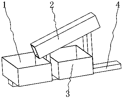
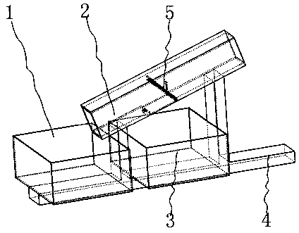
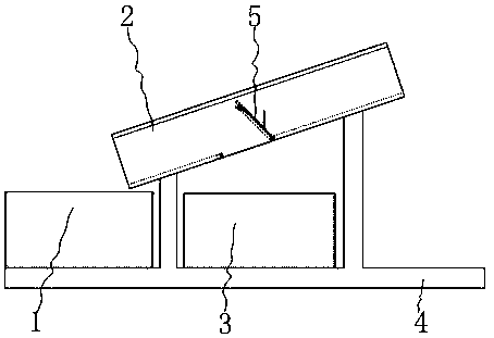
[0054] like figure 1 , 2 As shown, it includes a first collection box 1, a screening pipeline 2, a second collection box 3, a bracket 4, and a trigger screening plate 5, wherein as Figure 4 As shown, there are two shaft holes 11 on both sides of the screening pipeline 2, and the screening square opening 6 is provided on the lower side of the screening pipeline 2, as Figure 5 As shown, one side of the screening square opening 6 is provided with a supporting groove 7, and the lower side of the supporting groove 7 is provided with an avoidance groove 8; When the front end of the support groove 7 opened on the pipeline 2 cooperates, the support groove 7 opened on the scree...


PUM


Abstract

The invention belongs to the technical field of screening and particularly relates to a ball-shaped object screening device for the package field. The ball-shaped object screening device comprises a first collecting box, a screening pipeline, a second collecting box, a support and a trigger screening plate. In the device, modularization is adopted in the trigger screening plate for screening, a traditional door structure and a swing plate are combined into one, and thus the trigger screening plate is convenient to install compared with a screening device in which a door structure and a swing plate are located on the upper side and the lower side correspondingly. According to the designed screening device, the upper portion of a screening pipeline does not need to be destroyed, the triggerscreening plate is directly installed on two shaft holes formed in the screening pipeline, and the installing cost is reduced. According to the designed screening device, triggering and screening of the device are achieved at the lower side of the screening pipeline, space needing for installing the trigger screening plate is small, and the utilization rate of the screening pipeline is high.

Description

[0001] Technical field [0002] The invention belongs to the technical field of screening, in particular to a spherical object screening device used in the packaging field. Background technique [0003] Nowadays, many items need to be packaged to prevent them from being damaged during handling and transportation, and the items need to be simply classified before packaging; [0004] At present, there is a sorting mechanism, as recorded in Chapter 14 of "Practical Mechanisms and Devices Atlas of Mechanical Design", when spherical objects come down from the hopper, they must pass through a door, which is also the spring lock of the swing door; it meets the standard size The ball will pass directly without touching the gate, but the gate is generally designed on the upper side of the pipe, and the lower side of the pipe is designed with a swing plate. When the oversized ball hits the gate on the upper side, the upper The door will control the swing of the swing plate on the lower...

Claims


Application Information

Patent Timeline
IPC IPC(8): B07B13/04B07B13/16B07B13/14
CPCB07B13/04B07B13/14B07B13/16
Inventor 马艳王益之赖江耀
Owner 平邑经发产业发展有限公司
Learn More