Construction method of self-priming municipal drainage system

A technology for a municipal drainage system and a construction method is applied in the construction field of a self-priming municipal drainage system, which can solve the problems of insufficient improvement efficiency, difficulty in predicting the development trend of urban construction, and high construction costs, and achieves the effect of great environmental protection significance.

Active Publication Date: 2020-11-17
安徽企路石工程技术开发有限公司
View PDF10 Cites 0 Cited by
  • Summary
  • Abstract
  • Description
  • Claims
  • Application Information

AI Technical Summary

Problems solved by technology

However, it was often difficult to predict the future urban construction development trend when the early urban drainage network was constructed, so it was generally set at a shallower position from the ground when it was constructed, which has led to the fact that most of the underpass road sections today are lower than The height of the original urban drainage network, so if the drainage system of the underpass road section is connected to the original urban drainage network, water conservancy facilities such as pumping stations must be installed on these road sections
Existing pumping stations are mainly driven by electric energy, which not only has high construction costs, but also generates huge energy consumption. When encountering heavy rain, the efficiency of upgrading is often insufficient, which can easily lead to water accumulation on the road, resulting in huge loss of personnel and property

Method used


Image

  • Construction method of self-priming municipal drainage system
  • Construction method of self-priming municipal drainage system
  • Construction method of self-priming municipal drainage system

Examples


Embodiment 1

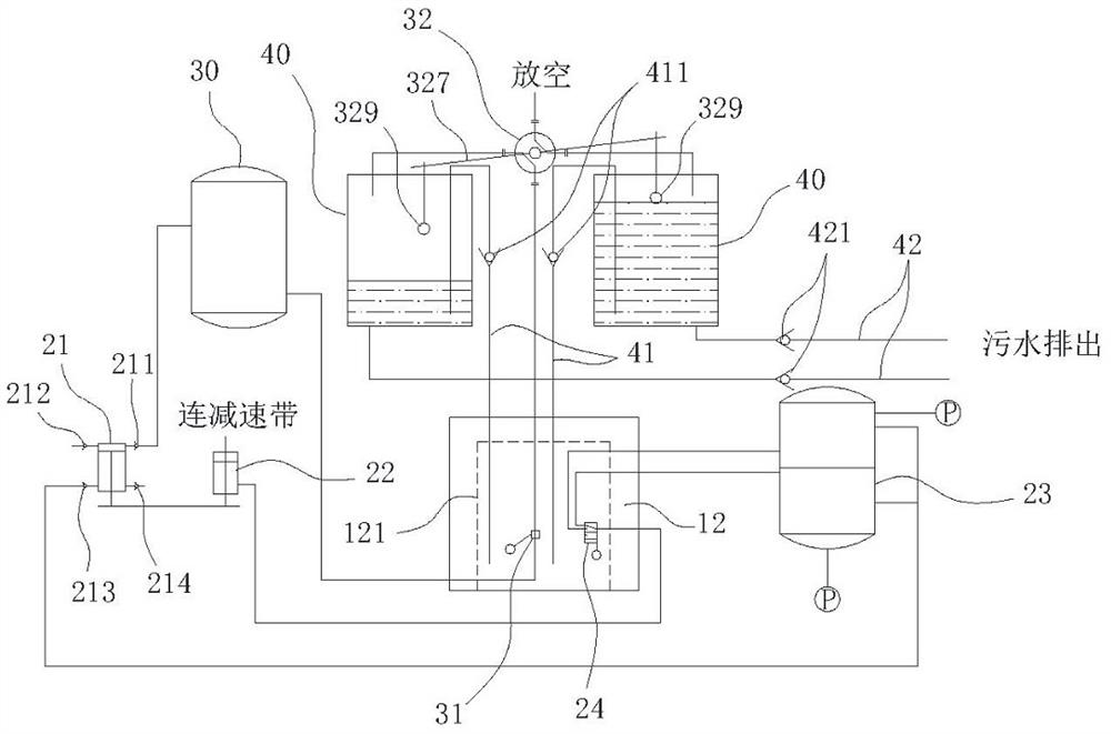
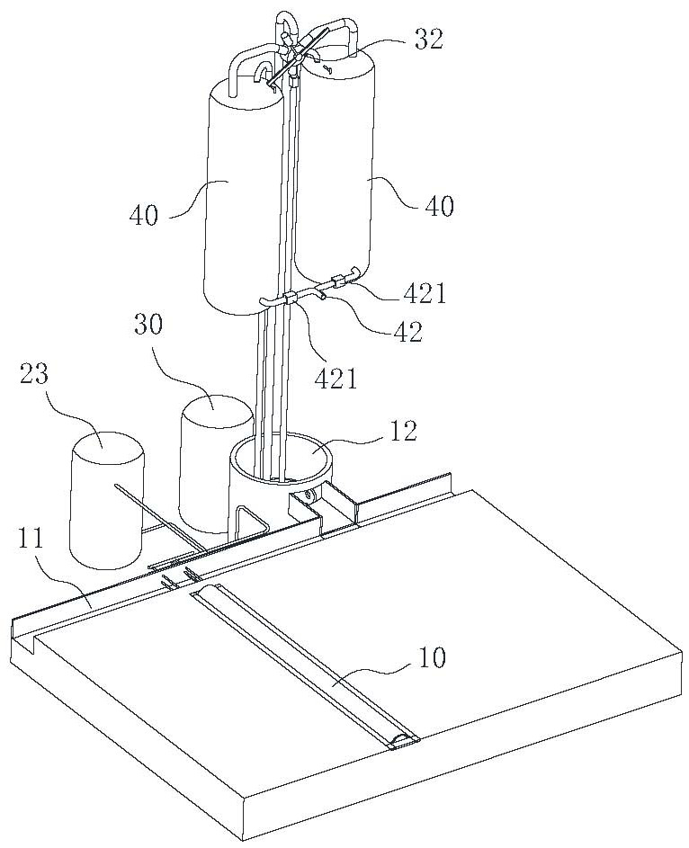
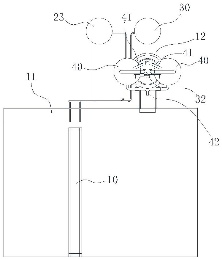
[0033] Such as figure 1 , 2 , 3, a low-lying road drainage system based on kinetic energy recovery, including a speed bump 10 arranged on the road surface, and a kinetic energy recovery device 20 arranged under the speed bump 10, the kinetic energy recovery device 20 is connected to the energy storage device, The energy storage device is connected with the suction device, one end of the suction device communicates with the drainage channel of the low-lying road surface, and the other end communicates with the urban drainage network. The present invention utilizes the kinetic energy recovery device 20 arranged under the deceleration belt 10 to recover the kinetic energy of the vehicle and temporarily stores it in the energy storage device. The accumulated water is pumped and drained into the urban drainage network. This invention does not need any external energy supply equipment. It is a simple and efficient road drainage solution. At the same time, the invention can recover ...

Embodiment 2

[0043] A construction method of a self-priming municipal drainage system, comprising the following steps:

[0044] S1: Excavate a strip-shaped foundation pit along the width direction of the road;

[0045] S2: installing the kinetic energy recovery device 20 in the foundation pit;

[0046] S3: Build installation positions for energy storage devices and suction devices on both sides of the road;

[0047] S4: install the energy storage device and the suction device, and connect the two, connect one end of the suction device to the inspection well 12 on both sides of the low-lying road, and connect the other end to the urban drainage network;

[0048] S5: connecting the kinetic energy recovery device 20 with the energy storage device;

[0049] S6: laying the deceleration belt 10 above the kinetic energy recovery device 20 .

[0050] In step S2, the kinetic energy recovery device 20 includes a vertically arranged first piston cylinder 21, and an elastic reset unit for driving t...


PUM


Abstract

The invention belongs to the technical field of municipal drainage, and particularly relates to a construction method of a self-priming municipal drainage system. The construction method comprises thefollowing steps of S1, excavating a strip-shaped foundation pit in the width direction of a road; S2, installing a kinetic energy recovery device in the foundation pit; S3, constructing installationpositions of energy storage equipment and a suction device on the two sides of the road; S4, installing the energy storage equipment and the suction device, connecting the energy storage equipment andthe suction device, communicating one end of the suction device into inspection wells on the two sides of a low-lying road surface, and communicating the other end of the suction device with an urbandrainage network; S5, connecting the kinetic energy recovery device with the energy storage device; and S6, laying speed bumps on the kinetic energy recovery device. By means of the construction method, no external connection of energy supply equipment is needed; the construction method is a simple and efficient road surface drainage solution; and meanwhile, the braking force of vehicles can be recovered and utilized, and the construction method has great environmental protection significance.

Description

technical field [0001] The invention belongs to the technical field of municipal drainage, and in particular relates to a construction method of a self-priming municipal drainage system. Background technique [0002] With the continuous expansion of the city, more and more intersections have begun to build three-dimensional traffic facilities such as elevated roads and underpasses to improve road traffic efficiency. With the reconstruction of these roads, the urban drainage system must also be upgraded accordingly. However, it was often difficult to predict the future urban construction development trend when the early urban drainage network was constructed, so it was generally set at a shallower position from the ground when it was constructed, which has led to the fact that most of the underpass road sections today are lower than The height of the original urban drainage network, so if the drainage system of the underpass road section is connected to the original urban dra...

Claims


Application Information

Patent Timeline
Patent Type & Authority Patents(China)
IPC IPC(8): F03G7/08E03F5/00E03F5/04E03F1/00E01F9/529
CPCE01F9/529E03F1/006E03F5/00E03F5/04
Inventor 储顺清郑书林刘成伟
Owner 安徽企路石工程技术开发有限公司
Why Eureka
Try Eureka