A real-time monitoring system and method for fiber optic cable core based on light source photodetector array

A photodetector, light source array technology, applied in transmission monitoring/testing/fault measurement systems, transmission systems, electromagnetic wave transmission systems, etc. Improve the efficiency of optical cable maintenance and management, reduce the incidence of optical cable failures, and reduce cable maintenance costs

Active Publication Date: 2022-01-14
STATE GRID HUBEI ELECTRIC POWER COMPANY INFORMATION & TELECOMM
View PDF3 Cites 0 Cited by
  • Summary
  • Abstract
  • Description
  • Claims
  • Application Information

AI Technical Summary

Problems solved by technology

[0003] Ⅰ. The maintenance team is huge and consumes a lot of manpower and material resources;
[0004] Ⅱ. The test period is too long, and the real-time performance of optical cable data is poor;
[0005] Ⅲ. The data management is complex and affected by human and process factors;
[0006] IV. Resource control is passive, and it is difficult to prevent failures in advance
[0007] V. There are problems such as incomplete measurement data and high instrument cost in manual instrument operation

Method used


Image

  • A real-time monitoring system and method for fiber optic cable core based on light source photodetector array
  • A real-time monitoring system and method for fiber optic cable core based on light source photodetector array
  • A real-time monitoring system and method for fiber optic cable core based on light source photodetector array

Examples


Embodiment Construction

[0034] The present invention will be described in detail below in conjunction with the accompanying drawings and specific embodiments.

[0035] (1) The overall structure of the system

[0036] Such as figure 1 As shown, the real-time monitoring system of fiber optic cable core based on light source photodetector array, its overall architecture is divided into three layers, as follows:

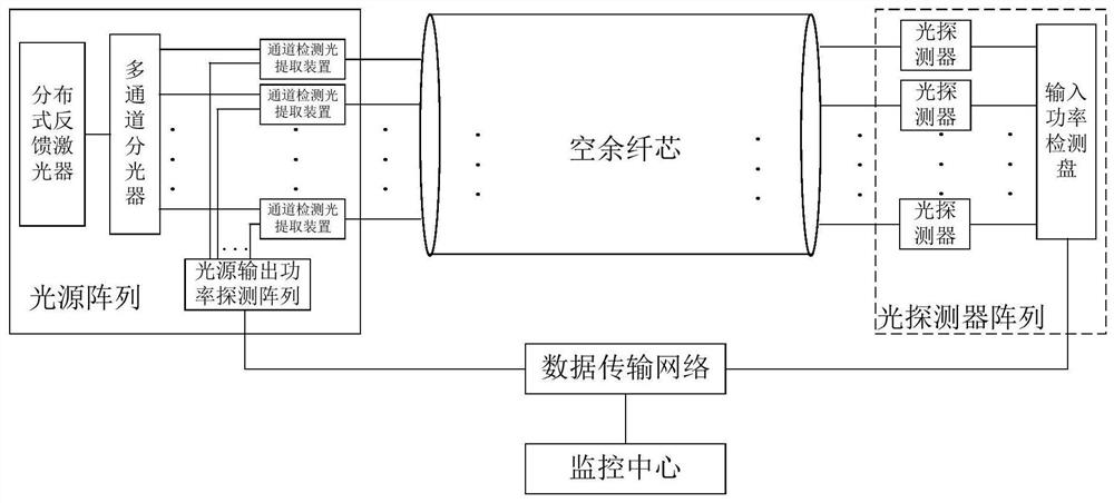
[0037] The bottom layer is the basic functional facilities, such as attached figure 1 As shown, it is mainly composed of three parts: the light source array, the photodetector array, and the spare fiber core in the optical cable link, and realizes the real-time measurement of the attenuation of the optical cable link. The data of the light source array and the photodetector array are transmitted to the monitoring center through the data transmission network of the optical fiber backbone network.

[0038] The middle layer is the monitoring server layer, including geographic information map, S...


PUM


Abstract

The present invention provides a real-time monitoring system and method for fiber optic cable cores based on light source photodetector arrays. Aiming at the monitoring and maintenance of fiber optic cable cores, the present invention uses a light source array to be set on a detection node of a spare fiber core in the running fiber optic cable. An optical detector array is set on the detection node at the opposite end of the fiber core to monitor the real-time power loss of the spare fiber core of the optical cable link in real time, and then analyze the monitoring data to provide link evaluation results and send corresponding alarm information, so as to realize optical power loss. The monitoring of the running status of the link replaces the manual measurement method after the link failure. The invention is based on the remote monitoring station, supported by a high-performance network communication processing system, and takes monitoring software as the core to provide complete and advanced centralized monitoring and comprehensive management functions for the optical cable links of the power communication network.

Description

technical field [0001] The present invention is a real-time monitoring system for optical fiber core based on a light source photodetector array. Aiming at information such as optical fiber degradation status and spare fiber core quality of communication optical cable, the light source photodetector array is used for monitoring, and a set of optical cable fiber core is constructed. Real-time monitoring system. The invention relates to the field of optical cable monitoring systems, in particular to the monitoring of optical cable fiber core quality and fiber core information management in electric power communication. Background technique [0002] With the development of communication technology, optical fiber communication has become the main technology choice for power communication, and the infrastructure of optical fiber communication is optical cable. In recent years, external damages such as municipal construction and accidents such as fires have led to an increasing r...

Claims


Application Information

Patent Timeline
Patent Type & Authority Patents(China)
IPC IPC(8): H04B10/07H04B10/079
CPCH04B10/07H04B10/07955H04B10/0791H04B10/079
Inventor 蒋燕王会洪孙志峰周智睿刘郑李熙殷天峰
Owner STATE GRID HUBEI ELECTRIC POWER COMPANY INFORMATION & TELECOMM
Why Eureka
Try Eureka