A defoaming stirring device

A stirring device and defoaming technology, applied in the direction of mixer accessories, transportation and packaging, foam dispersion/prevention, etc., can solve the problems of low stirring efficiency, slowing down production efficiency, difficulty in continuous and smooth preparation work, etc., to improve collection effect, the effect of improving collection efficiency

Active Publication Date: 2022-04-12
CHENGDU HAIRONG TECHNICAL TEXTILES CO LTD
View PDF11 Cites 0 Cited by
  • Summary
  • Abstract
  • Description
  • Claims
  • Application Information

AI Technical Summary

Problems solved by technology

[0002] In the production process of textile belts, some modifiers need to be configured on site. In most cases, agitators are required. However, the existing agitators have low stirring efficiency, and generally need to stir for 2 to 3 hours. or even longer, which greatly slows down productivity
At present, shear mixers are used to improve production efficiency and shorten mixing time, but they will generate a lot of foam, making it difficult to continue the smooth preparation work
This leads to a dilemma

Method used


Image

  • A defoaming stirring device
  • A defoaming stirring device
  • A defoaming stirring device

Examples


Embodiment

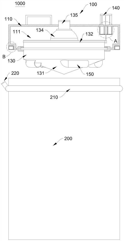
[0037] Please refer to Figure 1~3 , the present embodiment provides a defoaming type stirring device 1000, the defoaming type stirring device 1000 includes: a cover body 100, a barrel body 200, a foam pump (not shown in the figure) and a defoamer (not shown in the figure) .

[0038] The cover body 100 is detachably connected with the bucket body 200 , and the cover body 100 includes a cover body 110 , a rotating cylinder 130 and a suction tube 150 .

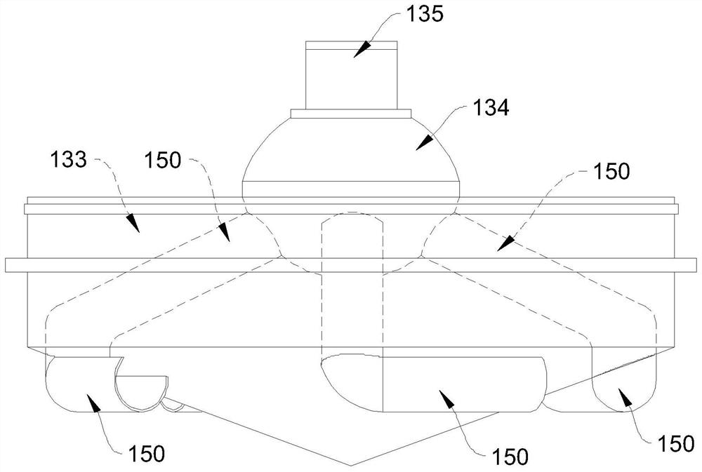
[0039] The rotating cylinder 130 is rotatably embedded in the cover body 110 and driven by the driver 140. The side of the rotating cylinder 130 close to the barrel body 200 protrudes in a conical shape, and the corresponding half top angle is 55-85°. In this embodiment, the corresponding half-vertex angle is set to 70°.

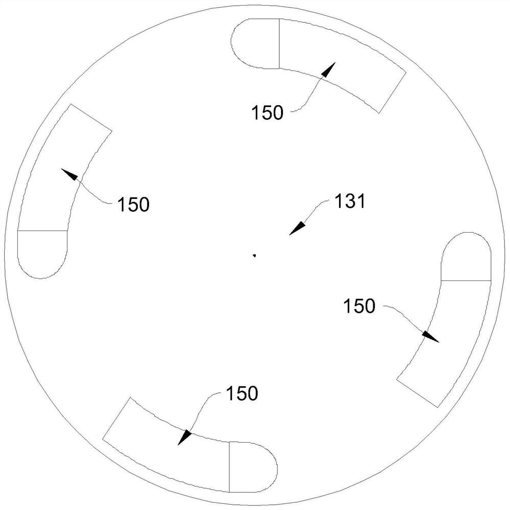
[0040]One end of the suction pipe 150 is attached to the conical wall 131 of the rotating cylinder 130 and extends along the circumferential direction of the conical wall 131. A plurality of suction pipes 15...


PUM


Abstract

A defoaming type stirring device relates to the field of textile belt production. Includes cover, barrel, foam pump and defoamer. The cover body is detachably connected with the bucket body, and the cover body includes a cover body, a rotating cylinder and a suction tube. The rotating cylinder is rotatably embedded in the cover body and is driven by the driver. The side of the rotating cylinder close to the barrel protrudes in a conical shape, and the corresponding half top angle is 55-85°. One end of the suction tube is attached to the conical wall of the rotating cylinder and extends along the circumference of the cone wall. A plurality of suction tubes are evenly spaced along the circumference of the conical wall, and the other end of the suction tube extends to the farthest One side of the barrel is in communication with the suction port of the foam pump. The other end of the foam pump communicates with the inlet of the defoamer, and the clear liquid outlet of the defoamer communicates with the barrel. Its structure is simple, easy to use, it has very high stirring efficiency and stirring effect, and effectively eliminates foam at the same time, which has a positive effect on improving production efficiency.

Description

technical field [0001] The invention relates to the field of textile belt production, in particular to a defoaming stirring device. Background technique [0002] In the production process of textile belts, some modifiers need to be configured on site. In most cases, agitators are required. However, the existing agitators have low stirring efficiency, and generally need to stir for 2 to 3 hours. Even longer, which greatly slows down productivity. At present, shear mixers are used to improve production efficiency and shorten mixing time, but they will generate a lot of foam, which makes it difficult for the preparation work to continue smoothly. This leads to a dilemma. [0003] In view of this, this application is proposed. Contents of the invention [0004] The object of the present invention is to provide a kind of defoaming stirring device, which is simple in structure, easy to use, has very high stirring efficiency and stirring effect, can greatly shorten the stirrin...

Claims


Application Information

Patent Timeline
Patent Type & Authority Patents(China)
IPC IPC(8): B01F33/80B01F35/30B01F35/45B01D19/02
CPCB01D19/02B01F33/80B01F33/836B01F35/325B01F35/3204B01F35/45
Inventor 李仲暄李平马元昌赵波肖雷朱伟明
Owner CHENGDU HAIRONG TECHNICAL TEXTILES CO LTD
Why Eureka
Try Eureka