Automatic wire clamp pressing device and wire clamp pressing method

An automatic and equipment technology, applied in the field of automation, can solve the problems of high purchase cost, achieve the effect of improving the pressing precision and quality of pressing, and improving the degree of automation and pressing efficiency

Pending Publication Date: 2019-11-12
JIANGSU CHUANGYUAN ELECTRON CO LTD
View PDF0 Cites 5 Cited by
  • Summary
  • Abstract
  • Description
  • Claims
  • Application Information

AI Technical Summary

Problems solved by technology

If the equipment is only used to press clamps of a single specification (type), it is necessary to purchase the corresponding type of equipment to press the clamps of each specification, which will lead to higher equipment purchase costs. The better technical solution is to design a Automatic crimping clamp equipment that meets multiple specifications of clamps

Method used


Image

  • Automatic wire clamp pressing device and wire clamp pressing method
  • Automatic wire clamp pressing device and wire clamp pressing method
  • Automatic wire clamp pressing device and wire clamp pressing method

Examples


Embodiment 1

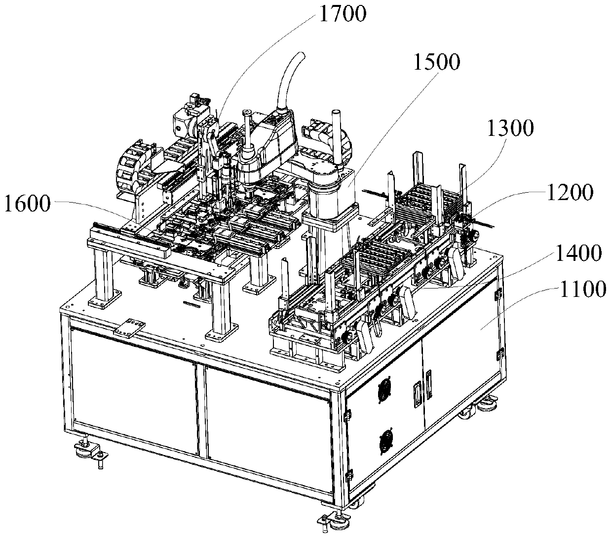
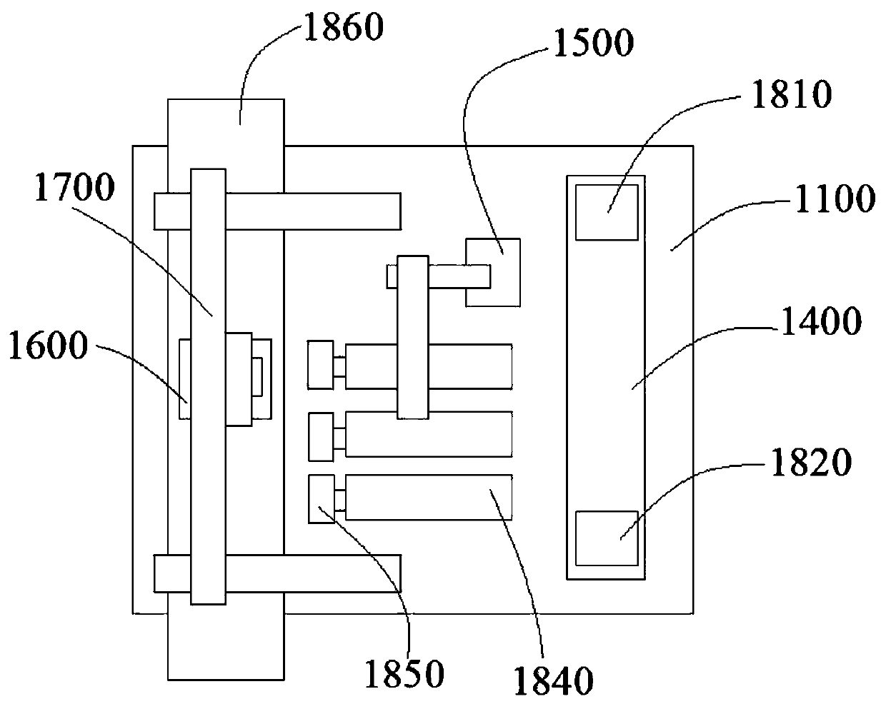
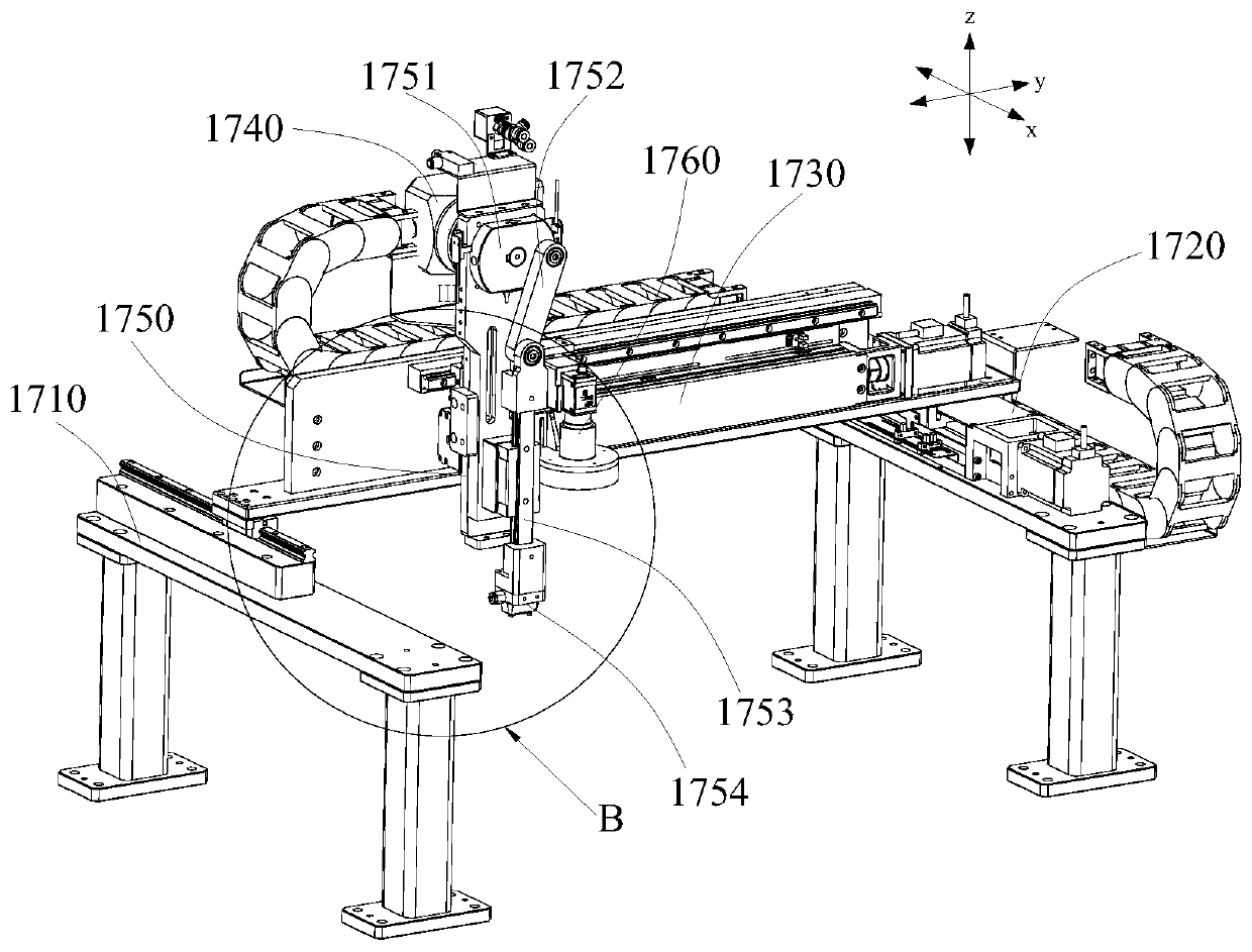
[0053] Such as Figure 1-Figure 4 As shown, an automatic wire crimping clamp equipment includes a crimping device 1700, and the crimping device 1700 includes a plane moving mechanism, a crimping mechanism 1750 and a visual guidance mechanism 1760 arranged on the plane moving mechanism; the crimping mechanism The lower end of 1750 is provided with an upper wire clamp 1871 acquisition mechanism and can press the obtained upper wire clamp 1871 on the lower wire clamp 1872. The visual guidance mechanism 1760 can take pictures of the upper wire clamp 1871, and the plane moving mechanism drives the press according to the photographing results The bonding mechanism 1750 moves to the pressing station. In this embodiment, after the acquisition mechanism acquires the upper wire clamp 1871, the visual guidance mechanism 1760 takes a picture of the upper wire clamp 1871 to obtain guidance information such as the position, shape, and size of the upper wire clamp 1871, and the planar moveme...

Embodiment 2

[0085] A kind of crimping clip method, comprises the following steps:

[0086] S1. The pressing device 1700 acquires the upper wire clamp 1871 and obtains the guide information of the upper wire clamp 1871 by taking pictures;

[0087] S2. Guide the crimping device 1700 to move to a corresponding position according to the guiding information to complete the crimping of the wire clips.

[0088] The upper wire clip 1871 is photographed before wire clip pressing to obtain guidance information. According to the guidance information, the pressing device 1700 can be accurately guided to move to the corresponding position for wire clip pressing, which improves the pressing accuracy and pressing quality.

[0089] It should be noted that the guide information includes parameters such as the position, shape, and size of the upper wire clamp 1871 . A wire crimping method in this embodiment can be realized by using the device in Embodiment 1.

[0090] Further, the step S1 includes:

[0...


PUM


Abstract

The invention discloses an automatic wire clamp pressing device and a wire clamp pressing method, and belongs to the technical field of automation. The automatic wire clamp pressing device comprises apressing device, wherein the pressing device comprises a plane moving mechanism, a pressing mechanism and a visual guide mechanism, and the pressing mechanism and the visual guide mechanism are arranged on the plane moving mechanism. An upper wire clamp obtaining mechanism is arranged at the lower end of the pressing mechanism and the pressing mechanism can press the obtained upper wire clamp ona lower wire clamp. The visual guide mechanism can photograph the upper wire clamp; the plane moving mechanism drives the pressing mechanism to move to a pressing station according to a photographingresult. The wire clamp pressing method comprises the following steps of S1, acquiring the upper wire clamp through the pressing device, and acquiring guide information of an upper wire clamp 1871 through photographing; and S2, guiding the pressing device to move to a corresponding position according to the guide information to complete wire clamp pressing. The wire clamp automatically-pressing device has the advantages that automation degree of the wire clamp pressing and quality of the wire clamp pressing are improved.

Description

technical field [0001] The invention relates to the technical field of automation, in particular to an automatic crimping clamp device and a crimping clamp method. Background technique [0002] The wire clamp is an accessory that can be fixed on the wire harness. Its functions include protecting the wire harness, ensuring electrical contact, and improving the orderliness of the wire harness. The wire clip can be composed of two parts that are detachably connected to each other, and the two parts need to be pressed together during installation. Most of the existing technologies use manual arrangement of wiring harnesses and press-fit installation of wire clips, which has a low degree of automation. The efficiency of manually pressing the clamps is low; the pressing force of each set of clamps cannot be precisely controlled, making it difficult to control the quality of the pressing, and there is a possibility that the clamps may fall off due to insufficient pressing force. ...

Claims


Application Information

Patent Timeline
Patent Type & Authority Applications(China)
IPC IPC(8): B23P19/00B23P19/02
CPCB23P19/001B23P19/02
Inventor 雍君苏亚东
Owner JIANGSU CHUANGYUAN ELECTRON CO LTD
Why Eureka
Try Eureka