
Yarn guide plate tilter for ring spinning frames

A technology of turning device and yarn guide plate is applied in spinning machine, continuous winding spinning machine, textile and paper making, etc. It can solve the problems of high labor intensity, long processing time and small location space, and reduce installation The effect of reducing workload, reducing labor intensity and speeding up installation time

Pending Publication Date: 2019-11-12
江阴市华方智能纺机装备有限公司
View PDF7 Cites 0 Cited by
  • Summary
  • Abstract
  • Description
  • Claims
  • Application Information

AI Technical Summary

Problems solved by technology

At present, in the existing yarn guide turning device, a group of yarn guide turning components are respectively arranged at both ends of the cylinder. When the cylinder moves up and down with the yarn guide, it will interfere with the machine beam, often causing collective doffing. The movement of the connecting rod is hindered to some extent, and the notch must be processed on the machine beam. The spinning mill requires no open flames, cutting machines, grinding wheels and other tools. The notch can only be processed manually with a hacksaw. Small size increases the workload of the installation workers, the processing time is long, the labor intensity is high, and it is difficult to ensure the position and shape of the gap, so there are safety problems during the installation and installation efficiency problems during the transformation

Method used


Image

  • Yarn guide plate tilter for ring spinning frames
  • Yarn guide plate tilter for ring spinning frames

Examples


Embodiment Construction

[0018] The present invention will be further described in detail below in conjunction with the accompanying drawings and embodiments.

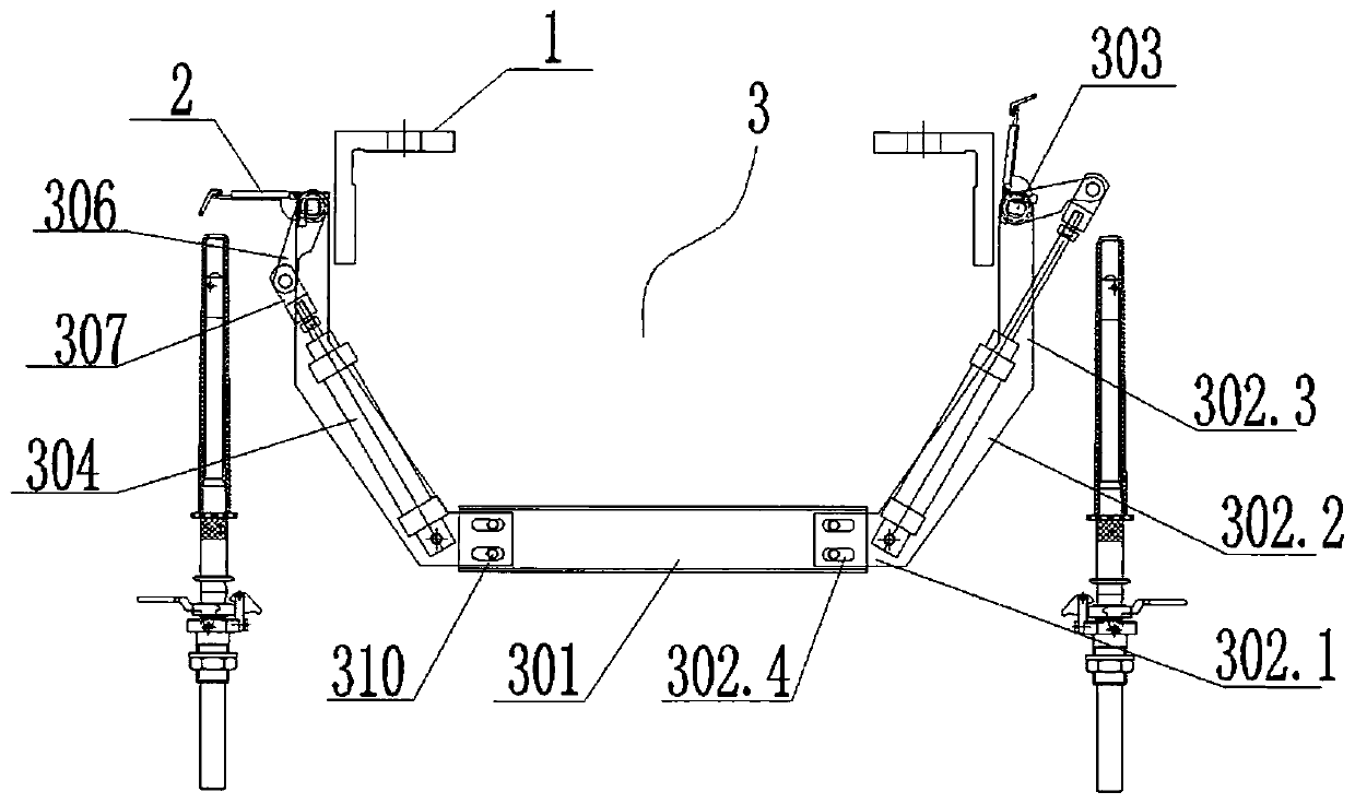
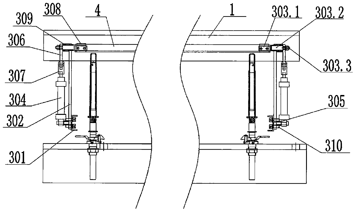
[0019] see Figure 1-Figure 2 , a ring spinning frame guide plate turning device related to the present invention, comprising a machine beam 1, an angle steel 4 is respectively arranged on the left and right sides of the machine beam 1, and a yarn guide plate 2 is arranged on the angle steel 4, so The bottom of the machine beam 1 is provided with two front and rear turning assemblies 3, which are respectively located on the front and rear sides of the angle steel 4. The turning assembly 3 includes a horizontally arranged fixed plate 301, and the two fixed plates 301 A support plate 302 is provided at each end respectively, the bottom end of the support plate 302 is connected with the outer end of the fixed plate 301, and the top end of the support plate 302 is connected with the outer end of the angle steel 4 through the connector 303, the sup...


PUM


Abstract

The invention relates to a yarn guide plate tilter for ring spinning frames. The yarn guide plate tilter comprises a beam. A steel angle is arranged on each of the left and right sides of the beam; ayarn guide plate is arranged on each steel angle; tilting assemblies are arranged at the front and rear of the two steel angles. Each tilting assembly comprises a fixing plate, and each end of the fixing plate is upwardly provided with a support plate; one end of each support plate is connected with the outer end of the corresponding fixing plate, and the other end of the support plate is connected with the outer end of the corresponding steel angle through a connector; a cylinder having a telescopic end facing up is arranged on each support plate, the fixed end of the cylinder is connected with the corresponding support plate through a cylinder seat, and the telescopic end of the cylinder is provided with a rotary arm sleeving the corresponding connector. The yarn guide plate tilter herein has no need for processing a gap for the beam, so that mounting workload for modification of an integrated doffer is reduced; the yarn guide plate tilter has the advantages of lower labor intensity,shorter mounting time and lower mounting expense.

Description

technical field [0001] The invention relates to an overturning device for a yarn guide plate of a ring spinning frame, belonging to the technical field of textile machinery equipment. Background technique [0002] The spinning process is the last process in the spinning process. The semi-finished roving produced in the previous process is spun into a spun yarn with a certain thickness and quality that meets the user's quality requirements through the spinning frame. During the spinning process, the doffing is realized by the yarn guide plate turning device. At present, in the existing yarn guide turning device, a group of yarn guide turning components are respectively arranged at both ends of the cylinder. When the cylinder moves up and down with the yarn guide, it will interfere with the machine beam, often causing collective doffing. The movement of the connecting rod is hindered to some extent, and the notch must be processed on the machine beam. The spinning mill requir...

Claims


Application Information

Patent Timeline
Patent Type & Authority Applications(China)
IPC IPC(8): D01H9/04D01H1/20
CPCD01H9/04D01H1/20
Inventor 沈宏李生伟蔡永良潘春平蒋浩勋
Owner 江阴市华方智能纺机装备有限公司
Learn More