Swing stopping device of push-pull door

A sliding door and swing stop technology, which is applied to door/window accessories, wing leaf components, wing leaf suspension devices, etc., can solve the problem of shortened service life of swing stoppers, easy wear and tear of rubber adjustment pads, and complicated production processes. and other problems, to achieve the effect of prolonging the service life, saving human and financial resources, and low cost.

Pending Publication Date: 2019-11-12
SHANGHAI TEMAX TRADE CO LTD
View PDF0 Cites 2 Cited by
  • Summary
  • Abstract
  • Description
  • Claims
  • Application Information

AI Technical Summary

Problems solved by technology

[0004] But in the process of use, since the sliding door always slides back and forth on the anti-swing device, the rubber adjustment pad is easy to be worn, and the anti-swing device is easy to lose its original function, and it is difficult to play the role of anti-swing on the sliding door. , resulting in a greatly shortened service life of the entire shock absorber
Moreover, due to the small elastic expansion and contraction range of the rubber adjustment pad, the glass that can be adapted to the installation of different thicknesses is also very limited, resulting in a greatly reduced scope of application.
In addition, the production process of the existing anti-shock device is relatively complicated in the production process, which is inconvenient to produce and wastes a lot of manpower and financial resources.

Method used


Image

  • Swing stopping device of push-pull door
  • Swing stopping device of push-pull door
  • Swing stopping device of push-pull door

Examples


Embodiment Construction

[0037] The following will clearly and completely describe the technical solutions in the embodiments of the present invention with reference to the accompanying drawings in the embodiments of the present invention. Obviously, the described embodiments are only some, not all, embodiments of the present invention.

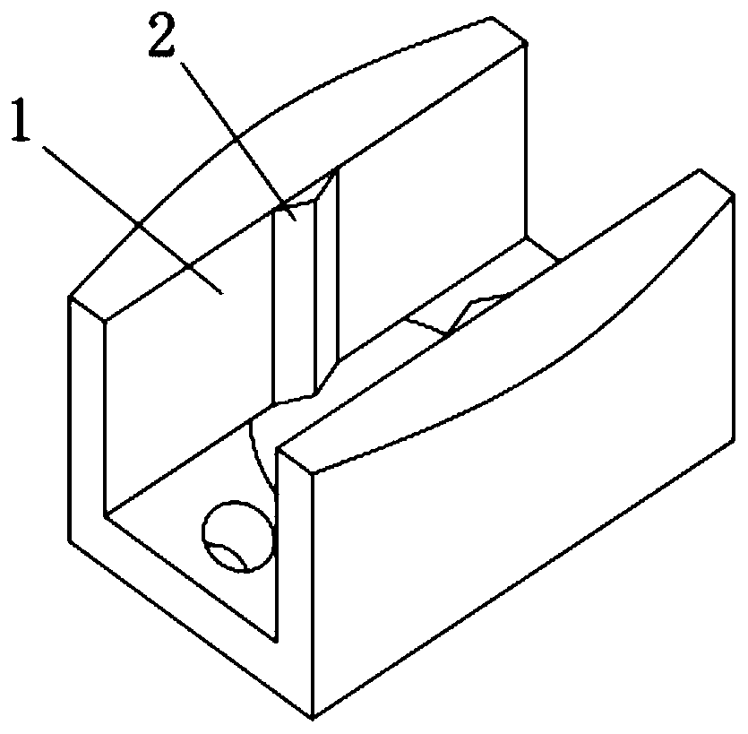
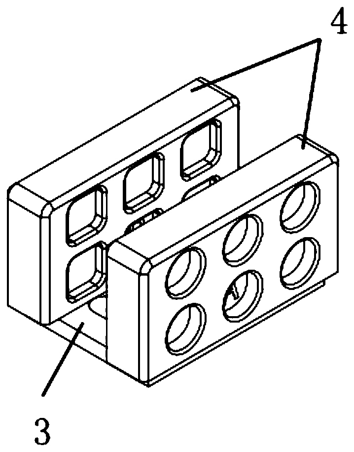
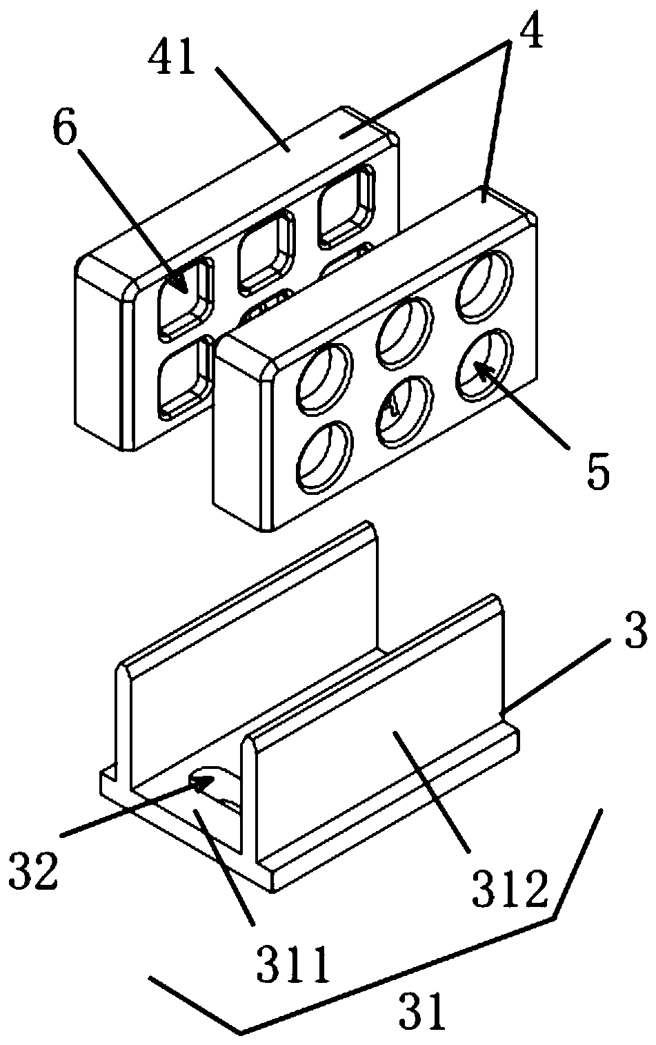
[0038] like Figure 2-3 As shown, a swing stopper for a sliding door includes a support mechanism 3 and an adjustment mechanism 4, wherein the support mechanism 3 includes a bracket 31 and a mounting hole 32, and the bracket 31 is composed of a bottom plate 311 and two vertically mounted on one side of the bottom plate 311. Two plug-in boards 312 are arranged parallel to each other. The two plug-in boards 312 are symmetrical about the vertical centerline of the bottom plate 311. The two plug-in boards 312 and the bottom board 311 are connected to form an integrated structure. The middle position of the board 312 is provided with a mounting hole 32; the adjustment mec...


PUM


Abstract

The invention discloses a swing stopping device of a push-pull door, and relates to the technical field of swing stopping devices. The swing stopping device of the push-pull door comprises a supporting mechanism and an adjusting mechanism, the supporting mechanism comprises a support and an installation hole, and the support is composed of a bottom plate and two insert plates installed verticallyon one side of the bottom plate; the adjusting mechanism comprises two adjusting sliding blocks, and insert grooves used in conjunction with the insert plates are formed in one sides of the two adjusting sliding blocks; the sections parallel to the bottom plate on the adjusting sliding blocks are arranged as first sections, sections parallel to the bottom plate on the insert grooves are arranged as second sections, and horizontal center lines of the first sections are not in the same line as horizontal center lines of the second sections. According to the swing stopping device of the push-pulldoor, by arranging the support and by the insert grooves being detachably installed on the two adjusting sliding blocks, the insert grooves on the adjusting sliding blocks are located in the non-center positions of the adjusting sliding blocks, the difference of the opposite side surfaces of the two adjusting sliding blocks is manually controlled to realize the distance between the two adjustingsliding blocks, the push-pull doors of different thickness are conveniently adjusted and adapted, the structure is simple, and the cost is low.

Description

technical field [0001] The invention relates to the technical field of swing stoppers, in particular to a swing stopper for sliding doors. Background technique [0002] Sliding door is a commonly used door in the family, which refers to a door that can be pushed and pulled. With the development of technology and the diversification of decoration methods, the function and scope of use of sliding doors are constantly expanding. Whether it is a square meter bathroom or an irregular storage room, as long as you replace it with a sliding door, no matter how small the space is, it will not be wasted. However, the sliding door swings left and right along its two sides during the moving process. In order to prevent the sliding door from swinging, a swing stopper for sliding doors has appeared on the market. [0003] Existing swing stops for sliding doors, such as figure 1 As shown, it consists of a base 1 with a U-shaped cross-section and an adjusting pad 2 that runs through the b...

Claims


Application Information

Patent Timeline
Patent Type & Authority Applications(China)
IPC IPC(8): E05D13/00E05D15/06
CPCE05D13/00E05D15/0656E05Y2900/132
Inventor 何锦洪
Owner SHANGHAI TEMAX TRADE CO LTD
Why Eureka
Try Eureka