Filtering connector with electromagnetic compatibility effect

A filter connector, electromagnetic compatibility technology, applied in the direction of connection, high-frequency structural connection, connection device components, etc., can solve the problem that the CE102 and RE102 indicators cannot meet the system-level requirements, and the shielding treatment method cannot meet the system-level electromagnetic Compatible with index requirements and other issues to achieve the effect of increasing adhesion

Active Publication Date: 2019-11-12
BEIJING MECHANICAL EQUIP INST
View PDF11 Cites 2 Cited by
  • Summary
  • Abstract
  • Description
  • Claims
  • Application Information

AI Technical Summary

Problems solved by technology

[0004] In view of the above analysis, the embodiment of the present invention aims to provide a filter connector with electromagnetic compatibility to solve the problem that the existing shielding treatment method for sensitive devices cannot meet the requirements of system-level electromagnetic compatibility indicators, especially CE102 and RE102 indicators Technical issues that do not meet system-level requirements

Method used


Image

  • Filtering connector with electromagnetic compatibility effect
  • Filtering connector with electromagnetic compatibility effect
  • Filtering connector with electromagnetic compatibility effect

Examples


Embodiment 1

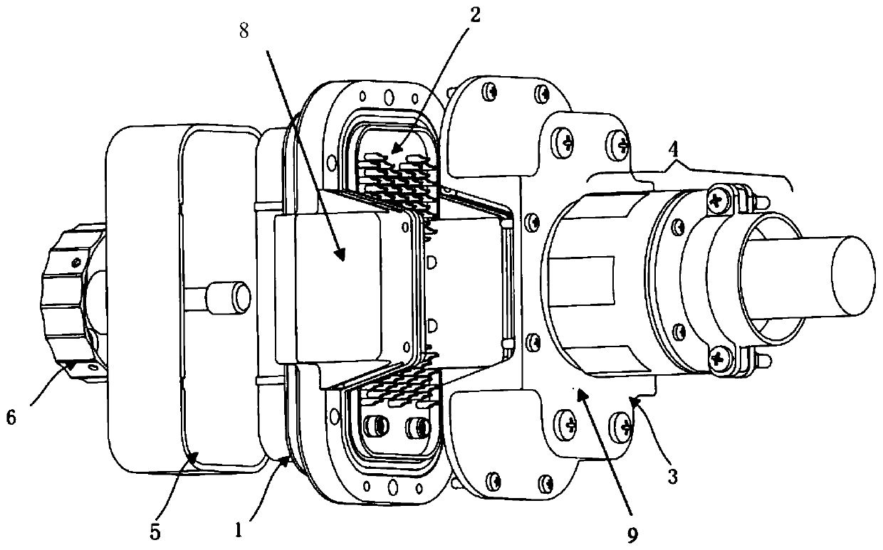
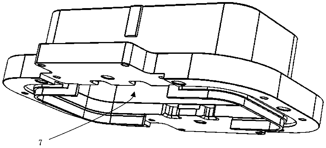
[0031] This embodiment provides a filter connector with electromagnetic compatibility, such as figure 1 with figure 2 As shown, it includes a filter connector body and a filter assembly 8 integrated on the filter connector body. The filter connector body includes a housing 1, a mounting plate, a contact assembly 2 and a printed circuit board; the mounting plate is arranged in the housing 1, and The board is set on the top of one side of the shell 1; the outer shell 1 is provided with a flange, and the two sides of the flange are provided with detachable filter components 8; the contact assembly 2 is provided on the mounting plate, and the mounting plate is also provided The first point contact, the second point contact, the third contact, and the fourth point contact. The filter assembly 8 adopts a π-type circuit and is in contact with the printed board, wires, and the first point to the fourth point. The whole circuit is connected with the filter connector.

[0032] Specificall...

Embodiment 2

[0045] The design principle of the filter circuit in the filter component 8 of the present invention is as attached Figure 5 As shown, in order to meet the product's insertion loss index, that is, the CE102 test required by GJB151B-2013, the insertion loss in the 200kHz~30MHz frequency band, the common mode and differential mode are not less than 25dB; according to the RE102 test requirements of GJB151B-2013 Test, such as Figure 5 As shown, it meets GJB151B-2013.

[0046] The above-mentioned filter component 8 uses a π-type circuit, where L1, L2, L3, L4>10mH; C1=C2=C3=1μF; C4=C5=47nF; Figure 5 As shown in the schematic circuit diagram, the calculation indicators of the insertion loss of CE102 and RE102 of the filter component 8 designed in the present invention are shown in Table 1 and Table 2, respectively:

[0047] Table 1 CE102 test filter component 8 insertion loss calculation index

[0048]

[0049] Table 2 Measured value of insertion loss of filter component 8

[0050]

[...


PUM


Abstract

The invention relates to a filtering connector with an electromagnetic compatibility effect, belongs to the technical field of electromagnetic compatibility devices of space limited systems, and solves the problem that an existing shielding processing device cannot meet CE102 and RE102 index requirements of system-level electromagnetic compatibility. The filtering connector comprises a filtering connector body, a filtering assembly, a dustproof unit and a sealing unit, wherein the filtering assembly, the dustproof unit and the sealing unit are integrated on the filtering connector body. The filtering connector body comprises a shell, a mounting plate, a contact element assembly and a printed board, wherein the mounting plate is arranged in the shell, the printed board is arranged at the top end of one side of the shell, the contact element assembly is arranged on the mounting plate, the filtering assembly is arranged on a flange plate outside the shell, the contact element assembly isprovided with first to fourth point contact elements, and the filtering assembly is connected with the first to fourth point contact elements through the printed board and wires. According to the invention, the filtering assembly is integrated on the connector of a limited space system-level cable, so that the power supply filtering function is realized.

Description

Technical field [0001] The invention relates to the technical field of electromagnetic compatibility design for restricted systems, and in particular to a filter connector with electromagnetic compatibility. Background technique [0002] Space-constrained system refers to a system that has strict requirements on the spatial layout, volume, and interface of the components in the system under a certain environment. This system generally exists in special equipment or precision instruments; such special equipment or precision instruments are not allowed to add new parts or change the interfaces of existing parts, and they also have strict requirements on space layout and volume. [0003] At present, the electromagnetic compatibility design for space-constrained systems only exists in the shielding treatment of sensitive devices; however, due to the increase in system-level electromagnetic compatibility index requirements, the existing shielding treatment methods cannot meet the system...

Claims


Application Information

Patent Timeline
Patent Type & Authority Applications(China)
IPC IPC(8): H01R13/719H01R13/52H01R13/523H01R13/502H01R13/504H01R13/512H01R13/648H01R13/6581H01R13/58H01R13/02
CPCH01R13/719H01R13/5213H01R13/5202H01R13/52H01R13/523H01R13/502H01R13/504H01R13/512H01R13/648H01R13/6581H01R13/5812H01R13/02
Inventor 李珊张雪玲
Owner BEIJING MECHANICAL EQUIP INST
Why Eureka
Try Eureka