Rotor punching piece, rotor and motor

A rotor punching and rotor technology, applied in electrical components, electromechanical devices, electric components, etc., can solve problems such as affecting motor performance, excessive magnetic flux leakage at the edge of the magnetic tile, and deterioration of motor torque ripple.

Active Publication Date: 2019-11-12
GUANDONG MEDIA INTELLIGENT TECH CO LTD
View PDF6 Cites 0 Cited by
  • Summary
  • Abstract
  • Description
  • Claims
  • Application Information

AI Technical Summary

Problems solved by technology

[0004] However, the applicant's technicians found in practice that in this surface-mounted rotor structure, there is more magnetic leakage at the edge of the magnetic tile, which affects the output torque of the motor; at the same time, irreversible demagnetization easily occurs at the edge of the magnetic tile, and the The maximum output torque will be limited, and the torque ripple of the motor will deteriorate, seriously affecting the performance of the motor

Method used


Image

  • Rotor punching piece, rotor and motor
  • Rotor punching piece, rotor and motor
  • Rotor punching piece, rotor and motor

Examples


Embodiment Construction

[0029] Specific embodiments of the present invention will be described in detail below in conjunction with the accompanying drawings. It should be understood that the specific embodiments described here are only used to illustrate and explain the present invention, and are not intended to limit the present invention.

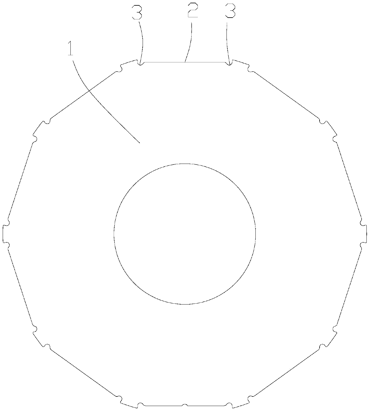
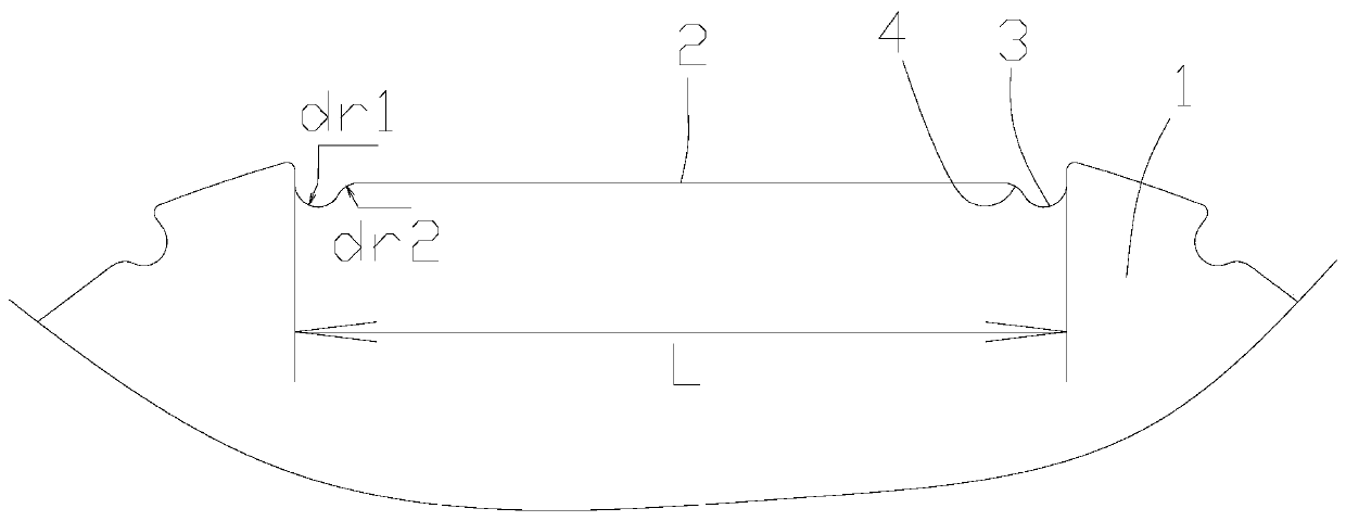
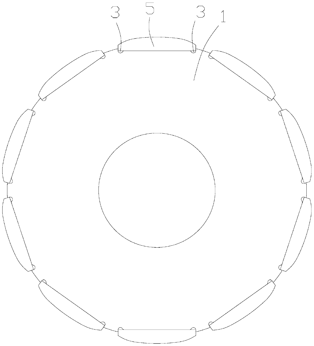
[0030] refer to figure 1 , figure 2 with image 3 , the outer peripheral surface of a rotor punch 1 provided by the present invention is formed with a plurality of magnetic tile receiving grooves 2 arranged at intervals in the circumferential direction, and the intervals between the plurality of magnetic tile receiving grooves 2 may be the same or not equal, wherein At least one of the positions corresponding to the ends of the magnetic tiles arranged in the magnetic tile accommodating groove 2 on the groove bottom surface of the magnetic tile accommodating groove 2 is formed with a radially inwardly extending concave cavity 3, for example, as figure 1 As sh...


PUM


Abstract

The invention relates to the technical field of motors, and discloses a motor punching piece, a rotor and a motor. A plurality of magnetic tile accommodating grooves are formed in a peripheral surfaceof the rotor punching piece and are circumferentially arranged at intervals, and a cavity is formed in at least one position in positions, corresponding to end parts of magnetic tiles arranged in themagnetic tile accommodating grooves, of groove bottom surfaces of the magnetic tile accommodating grooves and inwards extend in a radial direction. When the magnetic tiles are arranged in the magnetic tile accommodating grooves, avoidance spaces of the cavity are formed in two circumferential ends of the magnetic tiles, thus, the magnetic leakage of magnetic tile edges can be reduced under the condition that a main magnetic path of the magnetic tiles is not affected, and magnetic tile diamagnetism can be effectively reduced or prevented; and meanwhile, the torque pulse and cogging torque alsocan be reduced to a certain extent, so that the maximum output torque of the motor is improved, the motor efficiency is improved, and the application range of the motor is expanded.

Description

technical field [0001] The invention relates to the technical field of motors, in particular to a rotor punch, a rotor and a motor. Background technique [0002] At present, permanent magnet motors are more and more widely used in various industries due to their significant advantages such as high power density, good dynamic performance, and flexible shapes and sizes. The rotor structure of permanent magnet motors is currently roughly divided into two categories: surface mount type and built-in type. [0003] For the surface-mounted rotor structure, grooves are punched or cut out on the outer peripheral surface of the rotor punch. When multiple rotor punches are axially stacked, the grooves will form axially extending magnetic tile accommodation grooves, so that , the magnetic tiles can be directly arranged in the magnetic tile accommodating slots, so that the magnetic tiles are arranged on the entire outer peripheral surface of the rotor. [0004] However, the applicant's...

Claims


Application Information

Patent Timeline
Patent Type & Authority Applications(China)
IPC IPC(8): H02K1/22H02K1/27
CPCH02K1/22H02K1/274H02K2213/03
Inventor 赵丽丹丁伟兵李瑞磊周青松
Owner GUANDONG MEDIA INTELLIGENT TECH CO LTD
Why Eureka
Try Eureka