Signal transceiving device and electronic equipment

A technology for signal transmission and reception, electronic equipment, applied in the field of communication, can solve problems such as common antenna signal interference

Inactive Publication Date: 2019-11-12
VIVO MOBILE COMM CO LTD
View PDF7 Cites 11 Cited by
  • Summary
  • Abstract
  • Description
  • Claims
  • Application Information

AI Technical Summary

Problems solved by technology

[0005] The embodiment of the present invention provides a signal transceiving device and terminal equipment to solve the problem of signal interference in the common antenna in the existing terminal equipment

Method used


Image

  • Signal transceiving device and electronic equipment
  • Signal transceiving device and electronic equipment
  • Signal transceiving device and electronic equipment

Examples


no. 1 example

[0042] The signal transceiving device provided by the embodiment of the present invention will be described in detail below with reference to the accompanying drawings.

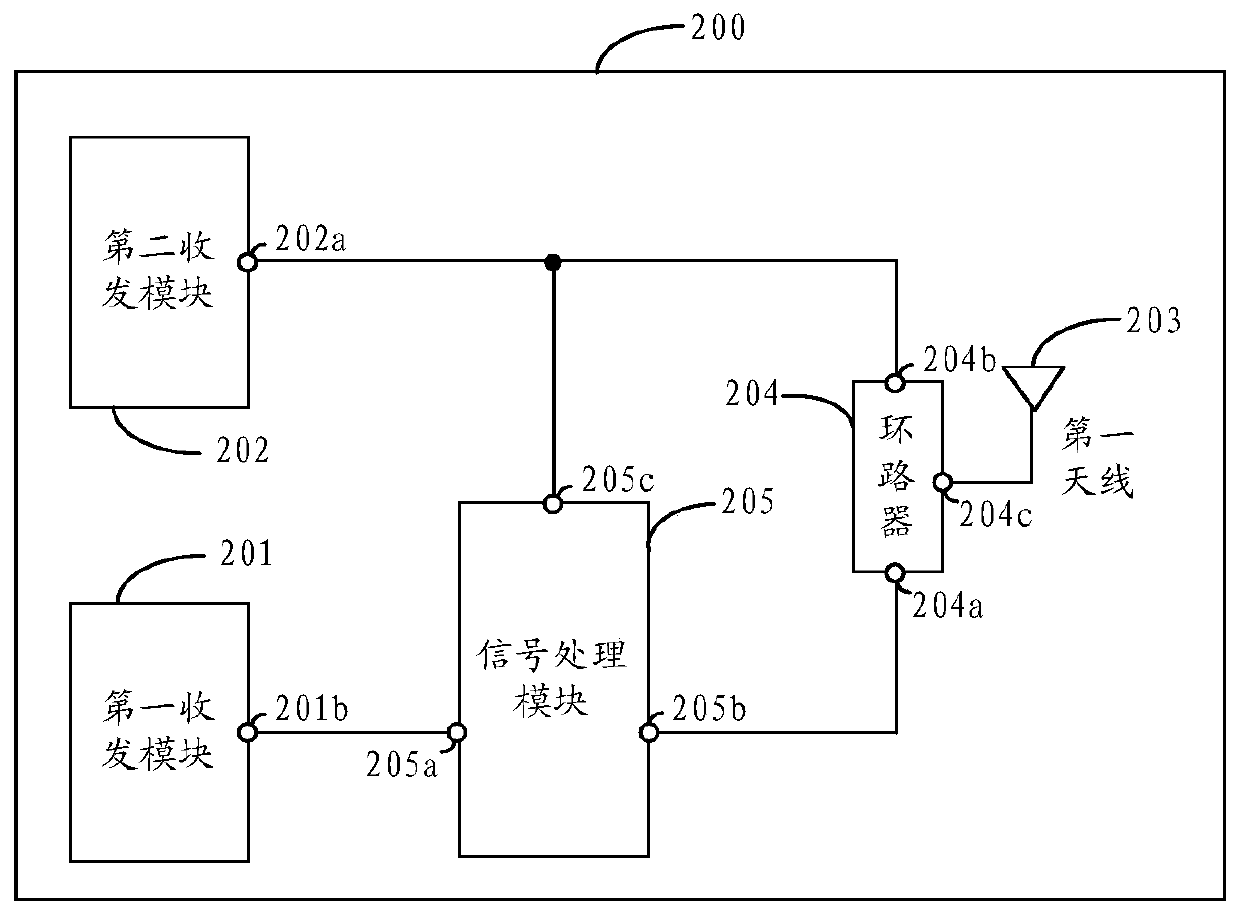
[0043] figure 2 A schematic structural diagram of a signal transceiving device provided for an embodiment of the present invention, such as figure 2 As shown, the signal transceiver device 200 includes: a first transceiver module 201, a second transceiver module 202, a first antenna 203, a looper 204, and a signal processing module 205, wherein: the output terminal 201b of the first transceiver module 201 is connected to the signal The input end 205a of the processing module 205 is connected; the first output end 205b of the signal processing module 205 is connected with the input end 204a of the looper 204, and the second output end 205c of the signal processing module 205 is connected with the input end 202a of the second transceiver module 202 It is connected with the transmission channel between the ou...

no. 2 example

[0089] An embodiment of the present invention provides an electronic device, and the electronic device includes the above-mentioned signal transceiving device. For a description of the specific structure of the signal transceiving device, reference may be made to the specific description in the above-mentioned first embodiment, which will not be repeated here.

[0090] Optionally, in the embodiment of the present invention, the above-mentioned electronic device further includes a processor, wherein:

[0091] A processor, configured to send the target phase offset and the target amplitude offset to the signal transceiving device, so that the signal transceiving device adjusts the interference in the second first signal of the two first signals according to the target phase offset The phase of the signal and the amplitude of the above-mentioned interfering signal are adjusted according to the target amplitude offset.

[0092] In the embodiment of the present invention, the above...


PUM


Abstract

The embodiment of the invention provides a signal transceiving device and electronic equipment, which are applied to the technical field of communication and are used for solving the problem that signal interference exists in a common antenna in the existing terminal equipment. The signal transceiving device comprises a first transceiving module, a second transceiving module, a first antenna, a loop device and a signal processing module, the signal processing module is used for splitting the first signal sent to the signal processing module by the first receiving and sending module into two paths of first signals, sending the first path of first signals to the loop device, obtaining and adjusting interference signals in the second path of first signals, and sending the adjusted interference signals to the input end of the second receiving and sending module; the loop device is used for sending the second signal to the second transceiver module; wherein the second signal comprises a first target signal received by the first antenna and an interference signal in the first path of first signal, the interference signal can be cancelled with the adjusted interference signal in the transmission channel, and the second transceiver module is used for receiving the first target signal.

Description

technical field [0001] Embodiments of the present invention relate to the technical field of communications, and in particular, to a signal transceiving device and electronic equipment. Background technique [0002] At present, in the 5G non-stand alone (NSA) networking architecture, the signal transceiver end of the terminal equipment is usually equipped with multiple antennas. At the same time, because the 4G base station and the 5G base station in the NSA networking architecture coexist, so The signal receiving end of the terminal device is equipped with a 4G antenna and a 5G antenna at the same time, so that the terminal device can send and receive 4G signals and 5G signals through the 4G antenna and the 5G antenna respectively. [0003] However, due to the limited internal space of terminal equipment, some existing terminal equipment uses one antenna to transmit 4G signals and receive 5G signals, that is, 4G TX (transmission) and 5G RX (reception) share the same antenna...

Claims


Application Information

Patent Timeline
IPC IPC(8): H04B1/40H04B1/401H04B1/50H04B1/10
CPCH04B1/40H04B1/50H04B1/401H04B1/10H04B1/1036
Inventor 肖石文李斌
Owner VIVO MOBILE COMM CO LTD
Why Eureka
Try Eureka