Mounting structure of fabricated movable frame type separation wall

A technology for moving frame and installation structure, applied in the direction of walls, building components, building structures, etc., can solve the problem of non-movable partition walls, and achieve the effects of easy disassembly, reduced building load-bearing, and high compressive and heavy-duty strength.

Pending Publication Date: 2019-11-15
GOLD MANTIS FINE DECORATION TECH SUZHOU CO LTD
View PDF0 Cites 3 Cited by
  • Summary
  • Abstract
  • Description
  • Claims
  • Application Information

AI Technical Summary

Problems solved by technology

[0004] In view of this, the present invention provides an assembly-type movable frame-type partition wall installation structure, which solves the problem that the partition wall cannot be moved, and can flexibly divide and adjust the space. method, no other cumbersome processes are required, the assembly process is simple, and the pressure resistance is high, the bearing capacity is strong, and it is green and environmentally friendly

Method used


Image

  • Mounting structure of fabricated movable frame type separation wall
  • Mounting structure of fabricated movable frame type separation wall
  • Mounting structure of fabricated movable frame type separation wall

Examples


Embodiment 1

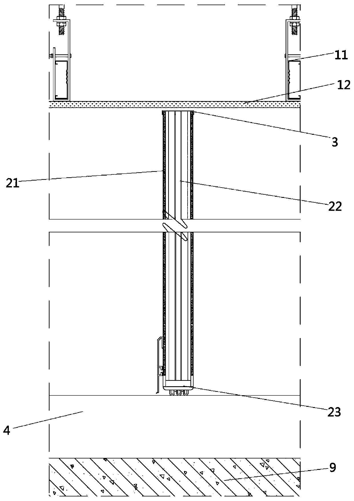
[0036] see Figure 1 to Figure 2 , Image 6 , the figure shows the installation structure of an assembled movable frame-type partition wall provided by Embodiment 1 of the present invention, the suspended ceiling, which includes a keel connector 11 connected to the top of the wall and a suspended ceiling layer 12, the keel connector 11 The bottom of the ceiling is connected with the suspended ceiling layer 12; the frame partition wall includes decorative wall panels 21 on both sides and a sound insulation laminate 22 arranged in the middle, the middle of the sound insulation laminate 22 is filled with sound insulation cotton, and the bottom of the frame partition wall is provided with Mobile wheel 23; top corner line 3, which is arranged between the suspended ceiling layer 12 and the frame partition wall, the side of the top corner line 3 is in the shape of “[”, the top of the frame partition wall is clamped in the top corner line 3, and the top corner line A non-contact stru...

Embodiment 2

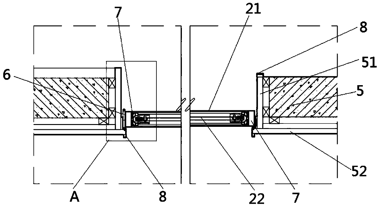
[0046] see Figure 1 to Figure 2 , Figure 5, the figure shows the installation structure of a prefabricated movable frame-type partition wall provided by Embodiment 2 of the present invention. On the basis of the above-mentioned embodiments, this embodiment further makes the following technical solutions as improvements One side of the frame partition wall is hinged to the side wall 5, and the two are connected by hinge 6 rotation; the outer side of the side wall 5 is provided with an outer frame 51, and one side of the outer frame 51 is provided with a limit plate 52; the limit plate 52 Anti-collision strips 53 are arranged on the inner side; connecting members 8 are also arranged on the edge of the outer frame 51 , and hook-shaped structures are arranged at both ends thereof. Through the setting of the above structure, the frame partition wall can be rotated along the side wall 5 through the hinge 6, and at the same time, there is an outer frame 51 between the two ends of ...

Embodiment 3

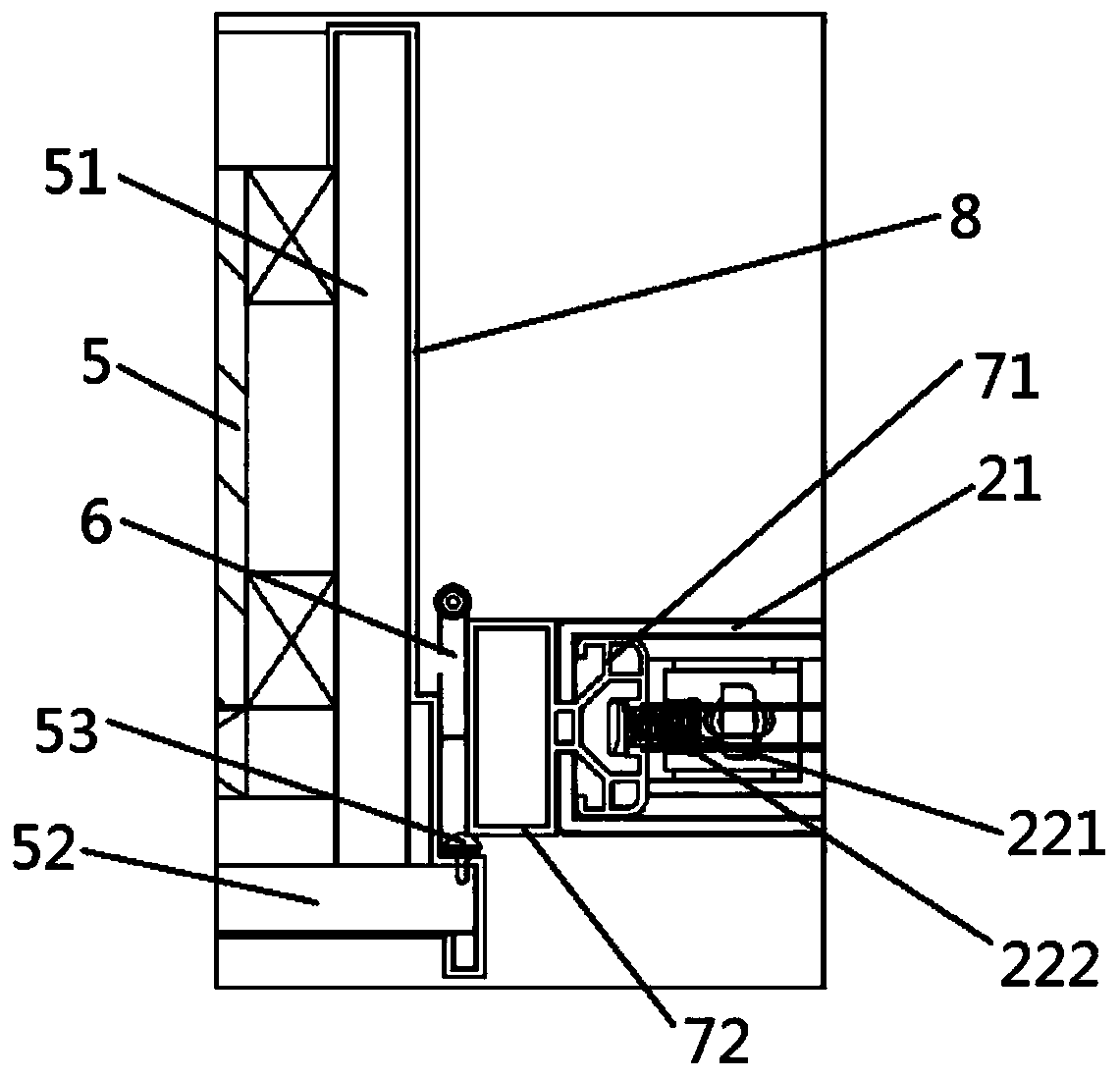
[0048] see Figure 1 to Figure 4 , the figure shows the installation structure of a prefabricated movable frame-type partition wall provided by Embodiment 3 of the present invention. On the basis of the above-mentioned embodiments, this embodiment further makes the following technical solutions as improvements : both sides of the decorative wallboard 21 are provided with a protective backing plate 7, the protective backing plate 7 is located between the side wall 5 and the decorative wallboard 21; the protective backing plate 7 includes a protective plate 71 and a connecting plate 72 arranged on the inner side of the protective plate 71 The connecting plate 72 is provided with a card slot 721 and a connecting slot 722, the card slot 721 is located on both sides of the connecting plate 72, and is located between the protective plate 71 and the connecting plate 72; the connecting slot 722 is located in the middle of the outer side of the connecting plate 72; The decorative wall ...


PUM


Abstract

The invention provides a mounting structure of a fabricated movable frame type separation wall. The mounting structure includes a furred ceiling, a frame separation wall, an apical angle line, and a ground decoration layer, wherein the furred ceiling includes a keel connection part and a furred ceiling layer, and the bottom of the keel connection part is connected with the furred ceiling layer; the frame separation wall includes a decorative wallboard and a sound insulation layer board, the sound insulation layer board is filled with sound insulation cotton, and a moving wheel is arranged at the bottom of the frame separation wall; the apical angle line is arranged between the furred ceiling layer and the frame separation wall, the side of the apical angle line is in a '[' shape, the top of the frame separation wall is clamped in the apical angle line, and a non-contact structure is arranged between the apical angle line and the furred ceiling layer; and the ground decoration layer isarranged on the ground, and the moving wheel is located in the ground decoration layer. Compared with the prior art, the mounting structure has the following advantages that the problem that the partition wall cannot be moved is solved, the space can be divided and adjusted flexibly, due to the fact that a site directly assembled dry operation construction method is adopted, other tedious processes are not required, the assembly process is simple, in addition, compression resistance is high, bearing force is strong, and environmental protection is achieved.

Description

technical field [0001] The invention relates to an installation structure of a movable frame-type partition wall, in particular to an installation structure of an assembled movable frame-type partition wall. Background technique [0002] Prefabricated decoration is a new form of decoration construction in recent years. As the name implies, prefabricated decoration is to complete the production of various parts and components required for decoration in the factory, and then transport them to the decoration site for assembly and installation, eliminating the need for traditional decoration on-site measurement and cutting of various parts and components. The construction is simpler and more convenient, which can greatly improve the construction efficiency of the decoration site, and the construction site is more tidy and beautiful, and will not produce too much decoration material waste. It is a more green and environmentally friendly form of decoration construction. [0003] ...

Claims


Application Information

Patent Timeline
Patent Type & Authority Applications(China)
IPC IPC(8): E04B2/74
CPCE04B2/74E04B2/7401E04B2/7403E04B2/7405
Inventor 何志伟于利凯阚靖琳
Owner GOLD MANTIS FINE DECORATION TECH SUZHOU CO LTD
Why Eureka
Try Eureka