Display device and backlight module

A display device and backlight module technology, which is applied in optics, nonlinear optics, instruments, etc., can solve the problems of small mini LED lamp boards and insufficient placement of diffuser board brackets

Inactive Publication Date: 2019-11-15
HISENSE VISUAL TECH CO LTD
View PDF17 Cites 9 Cited by
  • Summary
  • Abstract
  • Description
  • Claims
  • Application Information

AI Technical Summary

Problems solved by technology

However, the LED spacing of the mini LED light board is very small, generally less than 5mm, which is not enough to place the diffuser bracket, so the conventional method is difficult to achieve

Method used


Image

  • Display device and backlight module
  • Display device and backlight module
  • Display device and backlight module

Examples


Embodiment Construction

[0032] In order to make the purpose, technical solutions and advantages of the present invention clearer, the present invention will be further described in detail below in conjunction with the accompanying drawings. Obviously, the described embodiments are only some of the embodiments of the present invention, rather than all of them. Based on the embodiments of the present invention, all other embodiments obtained by persons of ordinary skill in the art without making creative efforts belong to the protection scope of the present invention.

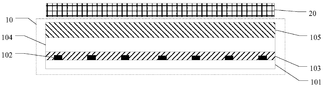
[0033] The first aspect of the embodiments of the present invention provides a display device, such as figure 1 As shown, the display device includes a backlight module 10 and a display panel 20 located on the light emitting side of the backlight module 10 .

[0034] The display panel 20 is located at the light emitting side of the backlight module 10 . It has a plurality of pixel units arranged in an array, and each pixel unit can ind...


PUM

PropertyMeasurementUnit
sizeaaaaaaaaaa
lengthaaaaaaaaaa
widthaaaaaaaaaa

Abstract

The invention provides a display device and a backlight module. The backlight module comprises a circuit board, multiple mini LEDs (light emitting diodes), a protective adhesive layer covering the multiple mini LEDs and the circuit board, a transparent substrate arranged on one side, deviating from the circuit board, of the protective adhesive layer and a diffusing plate arranged on one side, deviating from the circuit board, of the transparent substrate, wherein the thickness of the transparent substrate meets mixed light distances of the mini LEDs. The transparent substrate serves as a support structure between the protective adhesive layer and the diffusing plate, so that light emitted by the mini LEDs is sufficiently mixed before reaching the diffusing plate, and the backlight illumination effect is improved.

Description

technical field [0001] The invention relates to the field of liquid crystal display, in particular to a display device and a backlight module. Background technique [0002] High-Dynamic Range display technology (High-Dynamic Range, referred to as HDR), can provide more dynamic performance and image details, can better reflect the visual effects of objects in the real environment, and is generally considered to cause display The next revolution in the field. At the same time, HDR technology also puts forward higher requirements for LCD terminals - finer partition control and contrast. [0003] The size of a micro light emitting diode (mini LED) is about 50 μm-300 μm. Using a huge number of mini LED grains as a backlight source in the field of liquid crystal display can not only realize the thinning of the backlight module, but also achieve more refined dynamic control and improve the dynamic contrast of the liquid crystal display. [0004] In a traditional direct-lit backl...

Claims


Application Information

Patent Timeline
Patent Type & Authority Applications(China)
IPC IPC(8): G02F1/13357
CPCG02F1/133603G02F1/133606G02F1/133612
Inventor 李富琳
Owner HISENSE VISUAL TECH CO LTD
Why Eureka
Try Eureka