
Light guide plate and backlight module group

A technology of backlight module and light guide plate, applied in optics, light guide, light source and other directions, can solve the problem of increasing the thickness of the frame, and achieve the effect of avoiding lamp shadow, uniform brightness, and shortening the light mixing distance

Active Publication Date: 2012-08-01
TCL CHINA STAR OPTOELECTRONICS TECH CO LTD
View PDF6 Cites 0 Cited by
  • Summary
  • Abstract
  • Description
  • Claims
  • Application Information

AI Technical Summary

Problems solved by technology

However, in consideration of saving materials and reducing volume, it is not very desirable to increase the thickness of the frame

Method used


Image

  • Light guide plate and backlight module group
  • Light guide plate and backlight module group
  • Light guide plate and backlight module group

Examples


Embodiment Construction

[0023] see image 3 , image 3 It is a structural schematic diagram of the backlight module of the first embodiment of the present invention, such as image 3 As shown, in this embodiment, the backlight module mainly includes a light source 31 and a light guide plate 32 .

[0024] Wherein, there are multiple light sources 31 and they are arranged on the light incident side of the light guide plate 32 . In this embodiment, the light source 31 is an LED light source, including a plurality of LED chips. In other embodiments, the light source 31 may also be any other device capable of emitting light, which is not limited here.

[0025] The light guide plate 32 includes a bottom surface and a top surface opposite to the bottom surface. A plurality of microstructure units 33 are adjacently disposed on at least one of the top surface and the bottom surface of the light guide plate 32 near the light incident side. Wherein, each microstructure unit 33 corresponds to one LED chip, ...


PUM


Abstract

The invention discloses a light guide plate and a backlight module group. The light guide plate comprises a bottom surface and a top surface opposite to the bottom surface, wherein, multiple microstructure units are adjacently arranged on at least one of the top surface and the bottom surface of the light guide plate, which is close to a light incident side of the light guide plate; each microstructure unit comprises multiple strips of microstructures; and the multiple strips of microstructures in each microstructure unit extend on at least one of the top surface and the bottom surface of the light guide plate in a scattered manner. Through adopting the manner, the light guide plate has the advantages that light can be fully mixed within a shorter distance, so that the light mixing distance is shortened, and the brightness of the side light type backlight module group is enabled to be even on the premise that the thickness of a side frame of the side light type backlight module group is not increased, thereby avoiding lamp shadows.

Description

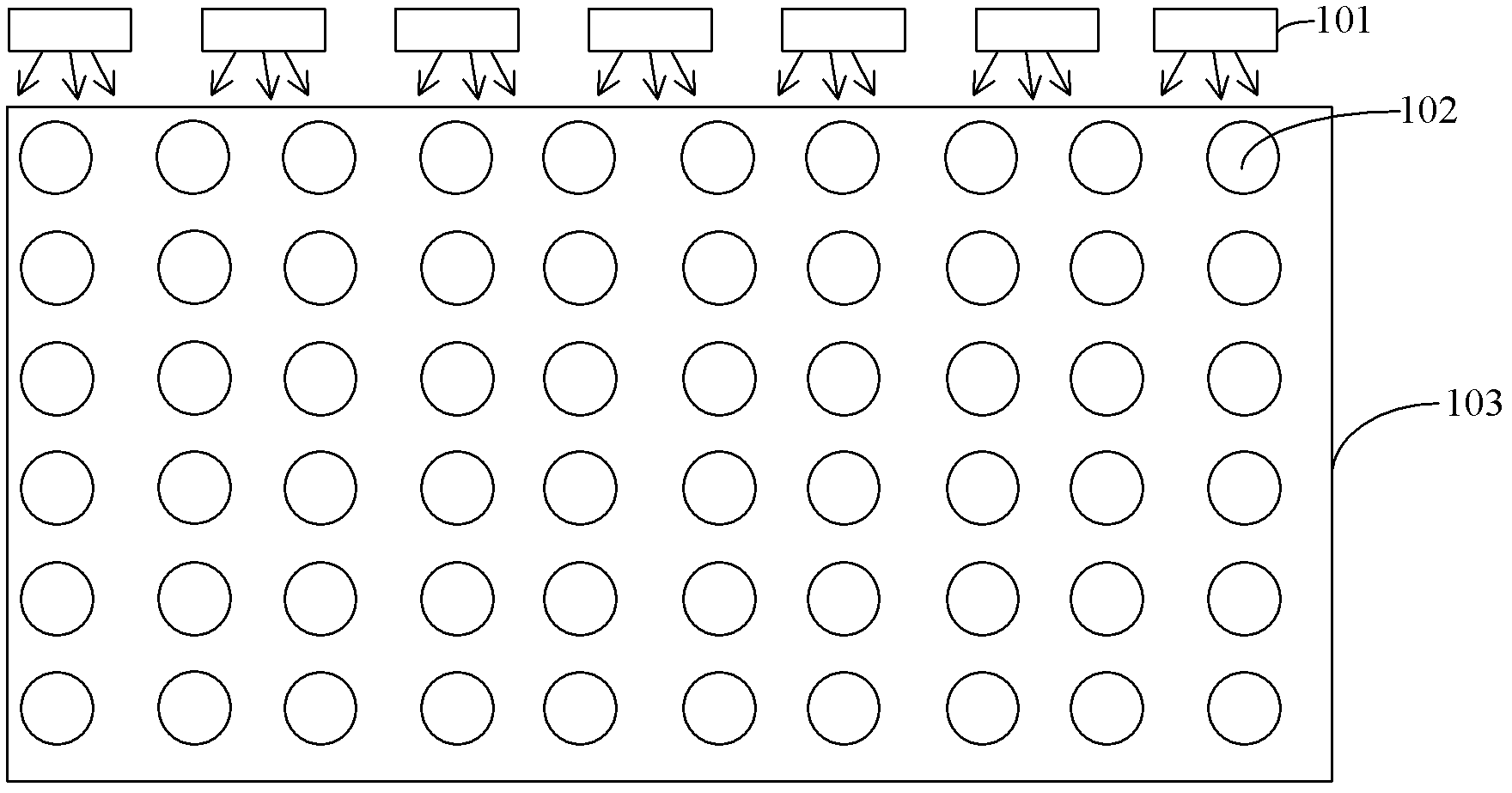
technical field [0001] The invention relates to the field of liquid crystal display, in particular to a light guide plate and a backlight module. Background technique [0002] Such as figure 1 as shown, figure 1 It is a schematic diagram of an edge-lit backlight module in the prior art. The light emitted from the LED light source 101 enters the light guide plate 103, wherein many dots 102 are set in the light guide plate 103. The incoming light acts as an even scatter. But the scattering effect of dots is relatively poor, moreover, because the refractive index (about 1.42) of light guide plate 103 is greater than the refractive index of air, therefore, its ray refraction angle will become smaller after the light from LED light source 101 enters light guide plate 103 . Such as figure 2 as shown, figure 2 It is a schematic diagram of the principle of the side-lit backlight module in the prior art. After the light emitted by the LED light source 201 enters the light gu...

Claims


Application Information

Patent Timeline
Patent Type & Authority Applications(China)
IPC IPC(8): G02B6/00F21S8/00F21V8/00F21Y101/02
CPCG02B6/0058G02B6/0038G02B6/00G02B6/0053
Inventor 黄建发
Owner TCL CHINA STAR OPTOELECTRONICS TECH CO LTD
Learn More