
A kind of LED light bar, backlight source and display device

A technology of LED light bar and light emitting surface, which is applied in the field of liquid crystal modules, can solve the problem of less outgoing light, reduce hotspot phenomenon, and improve the effect of insufficient luminous flux

Inactive Publication Date: 2016-11-23
BEIJING BOE DISPLAY TECH CO LTD +1
View PDF4 Cites 0 Cited by
  • Summary
  • Abstract
  • Description
  • Claims
  • Application Information

AI Technical Summary

Problems solved by technology

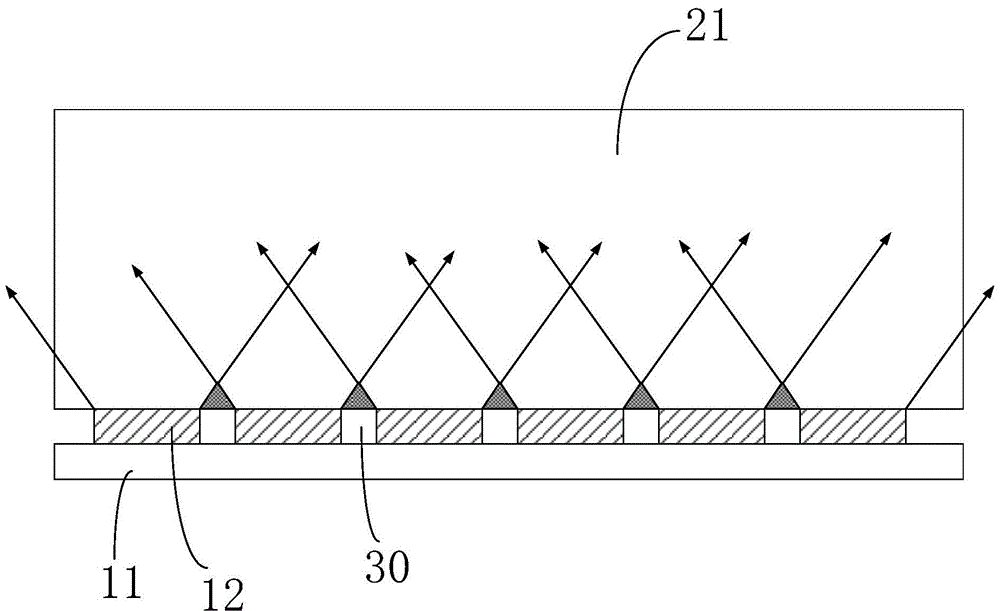
like image 3 As shown, the position of the gap 30 between adjacent LEDs 12 has no light that can be incident on the light guide plate 20, resulting in the output of the side of the light guide plate 20 that is close to the LED light bar at the position corresponding to the gap 30 between adjacent LEDs. There is less light, forming an area whose brightness is darker than the surrounding area, resulting in the phenomenon of hotspot (firefly) appearing on the display screen of the LCD module.

Method used


Image

  • A kind of LED light bar, backlight source and display device
  • A kind of LED light bar, backlight source and display device
  • A kind of LED light bar, backlight source and display device

Examples


Embodiment 1

[0050] Such as Figure 4 As shown, in this embodiment, the projection shape of the LED200 on the plane where the circuit board 100 is located is a parallelogram, and the parallelogram includes a first acute angle and a second acute angle arranged diagonally, wherein the first acute angle The corresponding portion forms the first protruding portion 2011 , and the portion corresponding to the second acute angle forms the second protruding portion 2021 .

[0051] In the above scheme, by improving the traditional cuboid LED200 into a parallelogram structure with an acute angle in section, the installation method and installation direction of each LED200 are the same, and the gap 300 between each LED200 and its adjacent LED200 forms an inclined The gap 300 , and each LED 200 and the protruding portion corresponding to the acute angle between its adjacent LEDs 200 cooperate with each other, and the projection on the first projection plane covers the gap 300 . After the LED 200 emit...

Embodiment 2

[0062] Such as Figure 6 As shown, in this embodiment, the projection shape of the LED 200 on the plane where the circuit board 100 is located is a trapezoid, and the trapezoid includes a third acute angle and a fourth acute angle, wherein the part corresponding to the third acute angle forms the The first protrusion 2011 is formed, and the part corresponding to the fourth acute angle forms the second protrusion 2021 . Further preferably, the trapezoid is an isosceles trapezoid.

[0063] In the above solution, the traditional rectangular parallelepiped LED200 is improved into a trapezoidal structure with an acute angle in cross section, and each LED200 is installed in the same way, but the installation directions of two adjacent LED200 are opposite, and they are installed alternately.

[0064] The first side end 201 of each LED200 is arranged close to the first side end 201 of its adjacent LED200, and forms a first gap with the first side end 201 of its adjacent LED200; the s...

Embodiment 3

[0069] Such as Figure 7 As shown, in this embodiment, the projection shape of the LED 200 on the plane where the circuit board 100 is located is a triangle, and the triangle includes a fifth acute angle and a sixth acute angle, wherein the part corresponding to the fifth acute angle forms the The part corresponding to the sixth acute angle forms the second protrusion 2021 . Further, the triangle is an isosceles triangle.

[0070]In the above solution, the traditional rectangular parallelepiped LED200 is improved to a triangular structure with an acute angle in section, and each LED200 is installed in the same way, but the installation directions of two adjacent LED200 are opposite, and they are installed alternately.

[0071] The first side end 201 of each LED200 is arranged close to the first side end 201 of its adjacent LED200, and forms a first gap with the first side end 201 of its adjacent LED200; the second side of each LED200 End 202 is arranged close to the second s...


PUM


Abstract

The present invention provides an LED light bar, a backlight source and a display device. The LED light bar includes a circuit board and a plurality of LEDs arranged on the circuit board at intervals along a first straight line, and a gap is formed between two adjacent LEDs. ; It is characterized in that the projections of two adjacent LEDs on the first projection plane at least partially overlap, and the first projection plane is a plane perpendicular to the circuit board and parallel to the first straight line. The LED light bar of the present invention can cover the gap in the direction perpendicular to the circuit board because two adjacent LEDs overlap at least partially in the projection direction perpendicular to the circuit board. When the LED light bar is applied to a backlight source, the LED After emitting light, there is at least a part of incident light at the position corresponding to the LED gap on the light guide plate, so that the light can be mixed up and down when propagating on the light guide plate, and the light can be mixed more fully, which improves the lack of luminous flux at the gap of the traditional LED light bar. phenomenon, thereby reducing the hotspot phenomenon.

Description

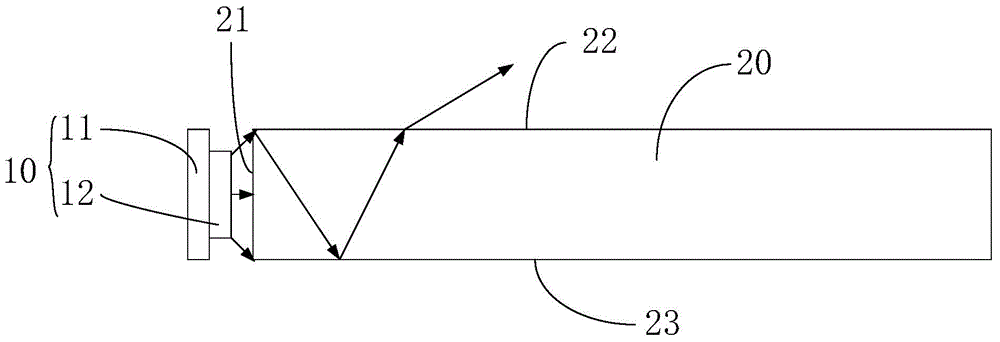
technical field [0001] The invention relates to the technical field of liquid crystal modules, in particular to an LED light bar, a backlight source and a display device. Background technique [0002] Such as figure 1 As shown, the backlight of a traditional liquid crystal module includes an LED light bar 10 and a light guide plate 20, etc., wherein the light guide plate 20 includes a light incident surface 21, a light exit surface 22 adjacent to the light incident surface 21, and a light exit surface adjacent to the light incident surface 21. On the bottom surface 23 opposite to the light-emitting surface 22, the LED light bar is arranged on the light-incident surface 21 side of the light guide plate 20, and the light emitted by the LED enters the light guide plate 20 to form total reflection and propagates in the light guide plate 20. When reaching the dots on the bottom surface 23 of the light guide plate 20, diffuse reflection occurs, which changes the original light pr...

Claims


Application Information

Patent Timeline
Patent Type & Authority Patents(China)
IPC IPC(8): F21S8/00F21V19/00G02F1/13357F21Y115/10
CPCG02F1/133603G02F1/133611G02F1/133615G02B6/0083G02B6/0068G02B6/0073F21V29/10
Inventor 王贺陶鹿堃柏玲布占场
Owner BEIJING BOE DISPLAY TECH CO LTD
Learn More