
Camera lifting device and mobile terminal

A lifting device and camera technology, applied in image communication, TV, color TV components and other directions, can solve the problems of low lifting efficiency and small transmission ratio, and achieve the effect of improving lifting efficiency and large transmission ratio

Pending Publication Date: 2019-11-15
SHENZHEN TRANSSION HLDG CO LTD
View PDF0 Cites 6 Cited by
  • Summary
  • Abstract
  • Description
  • Claims
  • Application Information

AI Technical Summary

Problems solved by technology

However, the existing lifting schemes all use screw drive, the transmission ratio is small, and the lifting efficiency is low

Method used


Image

  • Camera lifting device and mobile terminal
  • Camera lifting device and mobile terminal
  • Camera lifting device and mobile terminal

Examples


Embodiment Construction

[0042] The implementation of the present application will be described by specific specific examples below, and those skilled in the art can easily understand other advantages and effects of the present application from the content disclosed in this specification.

[0043] In the following description, reference is made to the accompanying drawings, which illustrate several embodiments of the application. It is to be understood that other embodiments may be utilized, and mechanical, structural, electrical, and operational changes may be made without departing from the spirit and scope of the present application. The following detailed description should not be considered limiting, and the scope of the embodiments of the present application is defined only by the claims of the issued patent. The terminology used herein is for describing particular embodiments only and is not intended to limit the application.

[0044] Although in some instances the terms first, second, etc. ar...


PUM


Abstract

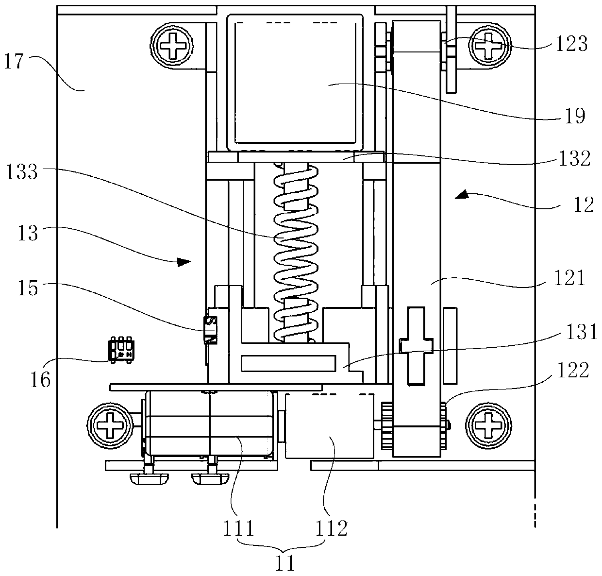
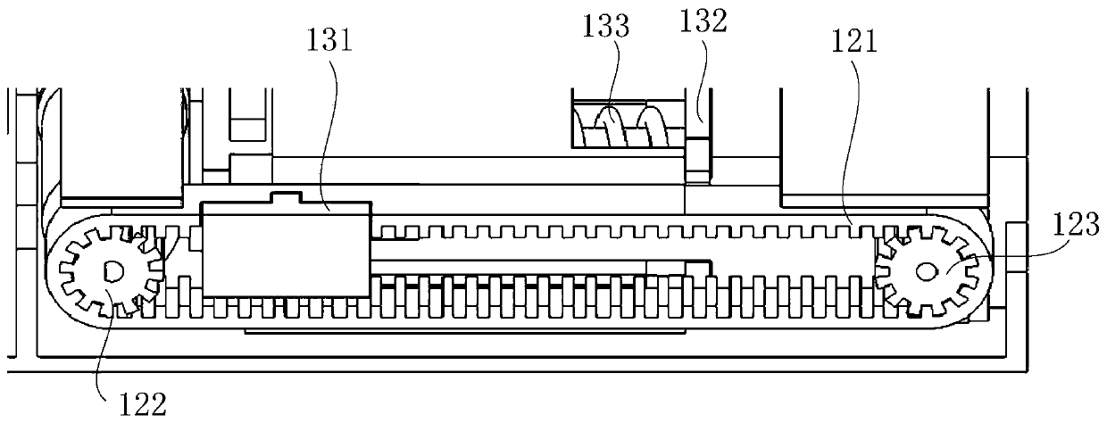
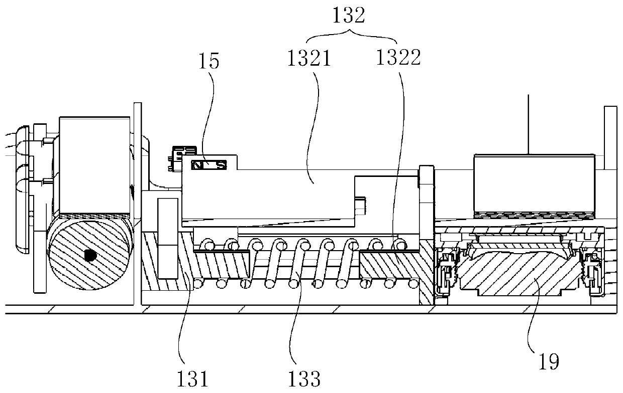
A camera lifting device comprises the components of a support which comprises a driving support, a connecting support and an elastic connecting piece, wherein the connecting support is used for fixinga camera, and the driving support abuts against the connecting support and is connected with the connecting support through the elastic connecting piece; a driving part which is used for providing power for driving the support to ascend and descend; and a gear rack transmission assembly which connects the driving piece with the driving support of the support. Transmission is conducted through thegear rack transmission assembly, the large transmission ratio can be achieved, the camera is driven to ascend and descend fast, and the lifting efficiency is improved.

Description

technical field [0001] The present application relates to the technical field of terminals, in particular to a camera lifting device and a mobile terminal. Background technique [0002] At present, maximizing the screen-to-body ratio is a design trend of mobile terminal devices represented by smart phones. Since the front camera must be placed on the side of the mobile phone screen, it brings great challenges to the full-screen design. [0003] Existing mobile terminals use a camera lifting scheme to realize rapid extension and retraction of the camera. The front of the screen of the mobile terminal does not need to open a camera hole, which can significantly improve the screen-to-body ratio and display effect of the front of the screen. However, the existing lifting schemes all adopt screw drive, the transmission ratio is small, and the lifting efficiency is low. Contents of the invention [0004] In view of the above technical problems, the present application provides ...

Claims


Application Information

Patent Timeline
Patent Type & Authority Applications(China)
IPC IPC(8): H04M1/02H04N5/225
CPCH04M1/0264H04N23/50H04N23/57
Inventor 何正文杨道庄王云峰黄丹
Owner SHENZHEN TRANSSION HLDG CO LTD
Learn More