
Reflector adjusting mechanism used on laser cutting machine

A technology of laser cutting machine and adjustment mechanism, which is applied in the direction of laser welding equipment, welding equipment, metal processing equipment, etc., and can solve the problems of single position and inability to adjust

Inactive Publication Date: 2019-11-19
安徽弘谷激光有限公司
View PDF10 Cites 1 Cited by
  • Summary
  • Abstract
  • Description
  • Claims
  • Application Information

AI Technical Summary

Problems solved by technology

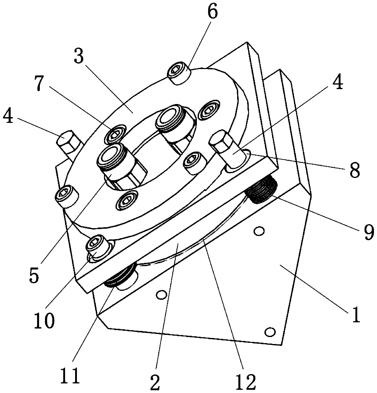
[0002] In the laser cutting machine, the use of the reflector is very important. The change of the height and angle of the reflector will have a direct impact on the laser cutting effect. At present, the position of the reflector body on the laser cutting machine is single and cannot be adjusted. Therefore, Provides a reflector adjustment mechanism for laser cutting machines, used to adjust the height and angle of the reflector through the reflector adjustment mechanism to obtain the best reflection effect, so that the laser cutting effect is improved

Method used


Image

  • Reflector adjusting mechanism used on laser cutting machine
  • Reflector adjusting mechanism used on laser cutting machine
  • Reflector adjusting mechanism used on laser cutting machine

Examples


Embodiment Construction

[0026] Specific embodiments of the present invention will be described in detail below in conjunction with the accompanying drawings. It should be understood that the specific embodiments described here are only used to illustrate and explain the present invention, and are not intended to limit the present invention.

[0027] In the present invention, unless otherwise specified, the orientation words included in the term such as "up, down, left, right, front, back, inside and outside" only represent the orientation of the term in the normal use state, or the common name understood by those skilled in the art. , and should not be construed as a limitation of this term.

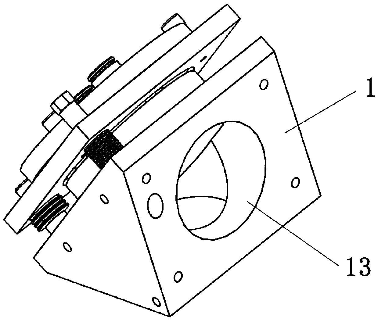
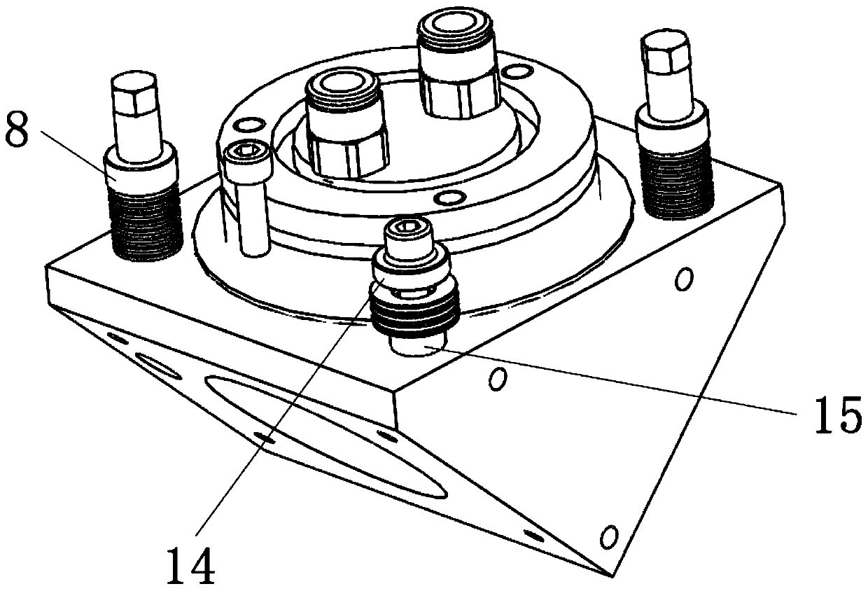
[0028] see Figure 1-3 The mirror adjustment mechanism used on the laser cutting machine shown, the mirror adjustment mechanism includes: a triangular prism base 1, one surface of the triangular prism base 1 faces the direction close to the triangular prism base 1 in the same order The shaft is provided with ...


PUM


Abstract

The invention discloses a reflector adjusting mechanism used on a laser cutting machine. A first through hole is formed in an adjusting plate, and a second through hole is formed in a fixing ring; a plurality of first threaded holes corresponding to first screws are formed in the adjusting plate, and a plurality of second threaded holes corresponding to second screws are formed in a reflector base; first adjusting holes are formed in the adjusting plate, screw pins are arranged in the adjusting holes, a second adjusting hole is formed in the adjusting plate, and a centripetal joint bearing isarranged in the second adjusting hole; and first adjusting screws are arranged in the screw pins, the end parts of the first adjusting screws are rotationally arranged on a triangular prism base, a second adjusting screw is fixedly inserted into the centripetal joint bearing, an outer thread is arranged at the end part of the second adjusting screw, and a screw gasket sleeve matched with the outerthread is fixedly connected to the triangular prism base. The reflector adjusting mechanism can be used for adjusting a reflector on the laser cutting machine.

Description

technical field [0001] The invention relates to a laser cutting machine, in particular to a reflective mirror adjustment mechanism for the laser cutting machine. Background technique [0002] In the laser cutting machine, the use of the reflector is very important. The change of the height and angle of the reflector will have a direct impact on the laser cutting effect. At present, the position of the reflector body on the laser cutting machine is single and cannot be adjusted. Therefore, Provided is a mirror adjustment mechanism used on a laser cutting machine, which is used to adjust the height and angle of the mirror through the mirror adjustment mechanism to obtain the best reflection effect, so that the laser cutting effect is improved. Contents of the invention [0003] The object of the present invention is to provide a reflector adjustment mechanism for a laser cutting machine, the reflector adjustment mechanism obtains the best reflection effect by adjusting the h...

Claims


Application Information

Patent Timeline
Patent Type & Authority Applications(China)
IPC IPC(8): B23K26/70B23K26/38
CPCB23K26/38B23K26/702
Inventor 张梅松
Owner 安徽弘谷激光有限公司
Learn More