Optical imaging lens

An optical imaging lens and lens technology, applied in optics, optical components, lenses, etc., to achieve high imaging quality

Pending Publication Date: 2019-11-19
ZHEJIANG SUNNY OPTICAL CO LTD
View PDF0 Cites 10 Cited by
  • Summary
  • Abstract
  • Description
  • Claims
  • Application Information

AI Technical Summary

Problems solved by technology

[0003] However, in order to achieve the characteristics of large image area, large aperture, and ultra-thin, new challenges have been put forward in the field of lens design. The previous five-element or six-element optical system structure is not enough to meet these challenges. Seven-element The traditional optical imaging system may gradually become the mainstream

Method used


Image

  • Optical imaging lens
  • Optical imaging lens
  • Optical imaging lens

Examples


Embodiment 1

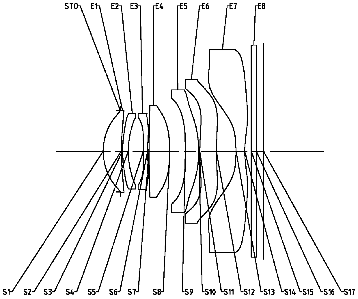
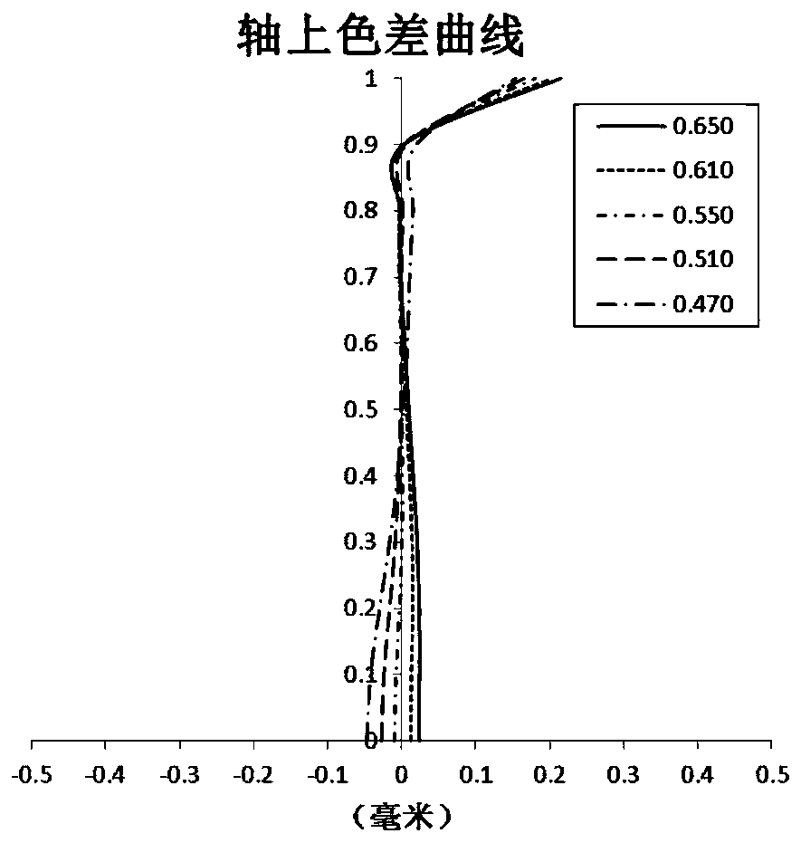
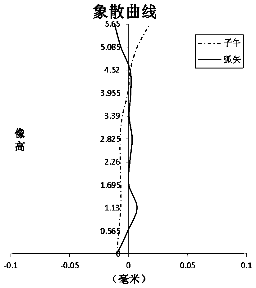
[0061] Refer to the following Figure 1 to Figure 2C An optical imaging lens according to Embodiment 1 of the present application is described. figure 1 A schematic structural diagram of an optical imaging lens according to Embodiment 1 of the present application is shown.

[0062] Such as figure 1 As shown, the optical imaging lens includes sequentially from the object side to the image side along the optical axis: a stop STO, a first lens E1, a second lens E2, a third lens E3, a fourth lens E4, a fifth lens E5, a sixth lens Lens E6, seventh lens E7, filter E8 and imaging surface S17.

[0063] The first lens E1 has positive refractive power, its object side S1 is convex, and the image side S2 is concave; the second lens E2 has positive refractive power, its object side S3 is convex, and the image side S4 is concave; the third lens E3 has a negative Refractive power, the object side S5 is convex, and the image side S6 is concave; the fourth lens E4 has positive refraction, ...

Embodiment 2

[0076] Refer to the following Figure 3 to Figure 4C An imaging lens according to Embodiment 2 of the present application is described. In this embodiment and the following embodiments, for the sake of brevity, descriptions similar to those in Embodiment 1 will be omitted. image 3 A schematic structural diagram of an optical imaging lens according to Embodiment 2 of the present application is shown.

[0077] Such as image 3 As shown, the optical imaging lens includes sequentially from the object side to the image side along the optical axis: a stop STO, a first lens E1, a second lens E2, a third lens E3, a fourth lens E4, a fifth lens E5, a sixth lens Lens E6, seventh lens E7, filter E8 and imaging surface S17.

[0078] The first lens E1 has positive refractive power, its object side S1 is convex, and the image side S2 is concave; the second lens E2 has positive refractive power, its object side S3 is convex, and the image side S4 is concave; the third lens E3 has a negat...

Embodiment 3

[0088] Refer to the following Figure 5 to Figure 6C An optical imaging lens according to Embodiment 3 of the present application is described. Figure 5 A schematic structural diagram of an optical imaging lens according to Embodiment 3 of the present application is shown.

[0089] Such as Figure 5 As shown, the optical imaging lens includes sequentially from the object side to the image side along the optical axis: a stop STO, a first lens E1, a second lens E2, a third lens E3, a fourth lens E4, a fifth lens E5, a sixth lens Lens E6, seventh lens E7, filter E8 and imaging surface S17.

[0090] The first lens E1 has positive refractive power, its object side S1 is convex, and its image side S2 is concave; the second lens E2 has negative refractive power, its object side S3 is convex, and its image side S4 is concave; the third lens E3 has Negative refractive power, the object side S5 is convex, and the image side S6 is concave; the fourth lens E4 has positive refractive p...


PUM


Abstract

The invention discloses an optical imaging lens, which sequentially comprises a first lens, a second lens, a third lens, a fourth lens, a fifth lens, a sixth lens and a seventh lens, which have refractive power, along an optical axis from an object side to an image side, wherein the first lens has positive refractive power; the third lens has negative refractive power; half ImgH of the length of adiagonal line of an effective pixel region on an imaging plane of the optical imaging lens meets the condition that ImgH is greater than 5mm; and the relative F number Fno of the optical imaging lensmeets the condition that Fno is smaller than 1.6.

Description

technical field [0001] The present application relates to an optical imaging lens, and more particularly, to an optical imaging lens including seven lenses. Background technique [0002] With the rapid development of portable electronic devices such as smart phones, consumers have higher and higher requirements for matching camera lenses on portable electronic devices. Especially for the main camera lens of smartphones, it is hoped that it can have the characteristics of large image area, large aperture, and ultra-thin at the same time. Large image area means higher pixels and imaging resolution; large aperture represents more effective luminous flux and higher signal-to-noise ratio during imaging, which is conducive to the image quality of night scenes and low light; ultra-thinness can be combined with smart The shape of the mobile phone achieves better compatibility and is easy to carry. Compared with the previous mobile phone lens specifications, changes in these main v...

Claims


Application Information

Patent Timeline
IPC IPC(8): G02B13/00G02B13/06G02B13/18
CPCG02B13/0045G02B13/06G02B13/18G02B9/64G02B3/04
Inventor 胡亚斌戴付建赵烈烽
Owner ZHEJIANG SUNNY OPTICAL CO LTD
Why Eureka
Try Eureka