
Double-shaft independent regulation and control motor

A technology of motor modules and motor housings, applied in the direction of electrical components, electromechanical devices, electric components, etc., can solve problems such as occupying a large position, inconvenient adjustment, and limiting the applicable field and scope of dual-output shaft motors, etc., to achieve Reduce the area occupied by the instrument, facilitate the maintenance and replacement of parts, and improve the utilization rate of the instrument and equipment

Pending Publication Date: 2019-11-19
SHANGHAI SHENGJIAN ENVIRONMENTAL SYST TECH
View PDF0 Cites 0 Cited by
  • Summary
  • Abstract
  • Description
  • Claims
  • Application Information

AI Technical Summary

Problems solved by technology

[0002] The traditional frequency conversion motor is a variable speed motor with a single output shaft, which can drive one load. If two loads need to be driven at the same time in the application, it will inevitably occupy a large position and is inconvenient to control
With the development of industry, for the full use of equipment, cost saving and space saving, double output shaft motors have emerged as the times require, but generally double output shaft motors only have one output shaft, and the speed and direction of rotation at both ends are the same, so they can only be rotated at the same time. Changing the size and direction greatly limits the applicable field and scope of the double output shaft motor. At this time, a motor with high integration, compact structure, high control precision, intuitive visualization, and independent control of the speed and direction of the two shafts is suitable for the current industry needs

Method used


Image

  • Double-shaft independent regulation and control motor
  • Double-shaft independent regulation and control motor
  • Double-shaft independent regulation and control motor

Examples


Embodiment Construction

[0044] The implementation of the present invention will be illustrated by specific specific examples below, and those skilled in the art can easily understand other advantages and effects of the present invention from the contents disclosed in this specification.

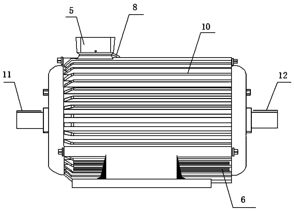
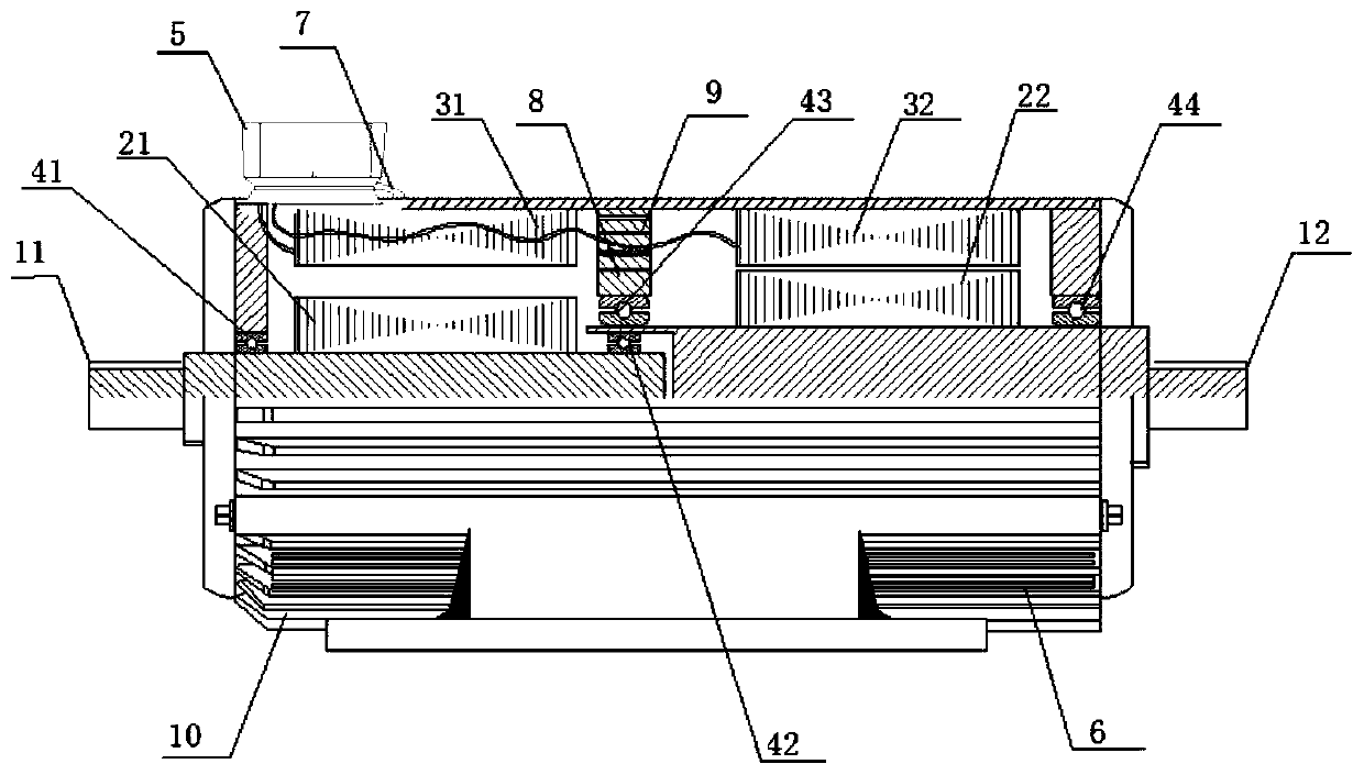
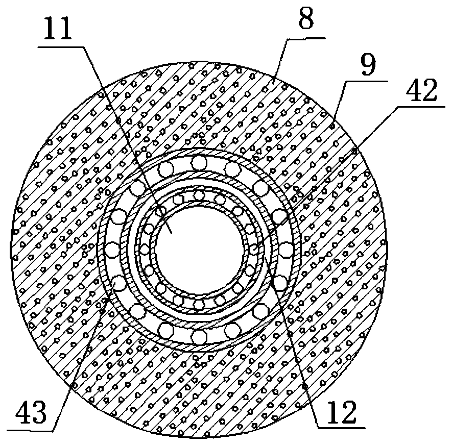
[0045] see Figure 1 to Figure 5 . It should be noted that the structures, proportions, sizes, etc. shown in the drawings attached to this specification are only used to match the content disclosed in the specification, for those who are familiar with this technology to understand and read, and are not used to limit the implementation of the present invention. Limiting conditions, so there is no technical substantive meaning, any modification of structure, change of proportional relationship or adjustment of size, without affecting the effect and purpose of the present invention, should still fall within the scope of the present invention. within the scope covered by the disclosed technical content. At the same ti...


PUM


Abstract

The invention provides a double-shaft independent regulation and control motor. The double-shaft independent regulation and control motor at least includes a rotating shaft, a rotor, and a stator. Therotating shaft at least includes a first rotating shaft 11 and a second rotating shaft 12. The rotor at least includes a first rotor 21 and a second rotor 22. The stator at least includes a first stator 31 and a second stator 32. The first rotor 21 and the second rotor 22 are arranged on the first rotating shaft 11 and the second rotating shaft 12. The first stator 31 and the first rotor 21 are cooperated to provide power to the first rotating shaft 11. The second stator 32 and the second rotor 22 are cooperated to provide power to the second rotating shaft 12. By using the double-shaft independent regulation and control motor, double shafts are independent and a rotating speed is accurately controlled; and steering can be switched randomly without changing a phase sequence or positive and negative connection of a power supply so as to achieve an arbitrary speed ratio and steering output of two ends of the rotating shaft.

Description

technical field [0001] The invention relates to the field of motor manufacturing, in particular to a dual-axis independent regulation motor. Background technique [0002] The traditional frequency conversion motor is a variable speed motor with a single output shaft, which can drive one load. If two loads need to be driven at the same time in the application, it will occupy a large position and it is inconvenient to control. With the development of industry, for the full use of equipment, cost saving and space saving, double output shaft motors have emerged as the times require, but generally double output shaft motors only have one output shaft, and the speed and direction of rotation at both ends are the same, so they can only be rotated at the same time. Changing the size and direction greatly limits the applicable field and scope of the double output shaft motor. At this time, a motor with high integration, compact structure, high control precision, intuitive visualizati...

Claims


Application Information

Patent Timeline
IPC IPC(8): H02K16/00H02K5/18H02K9/04
CPCH02K16/00H02K5/18H02K9/04
Inventor 张伟明刘倩汪哲
Owner SHANGHAI SHENGJIAN ENVIRONMENTAL SYST TECH
Learn More