
Pipe end opening efficient expanding machine

A flaring machine and port technology, which is applied in the field of high-efficiency flaring machines for pipe fittings, can solve the problems of inability to meet the needs of industrial production automation, high machine cost and maintenance cost, and low metal pipe processing efficiency, and achieve maintenance and replacement of parts and debugging. Convenience, low production cost, meet the effect of energy saving and emission reduction

Inactive Publication Date: 2020-09-29
秦喜顺
View PDF9 Cites 0 Cited by
  • Summary
  • Abstract
  • Description
  • Claims
  • Application Information

AI Technical Summary

Problems solved by technology

[0003] However, the working method of the above-mentioned belling machine depends on the proficiency and work experience of the staff, so the processing efficiency for metal pipes is low and cannot meet the automation needs of industrial production
In order to solve this technical problem, those skilled in the art also relate to the automatic belling machine of numerical control, yet adopt the automation structure design of numerical control to need to adopt a large amount of electronic components and high-precision driving and transmission parts, although the work efficiency of numerical control belling machine It can meet the needs of today's industrial production, but the cost and maintenance cost of the machine are relatively high, and the angle of the required parts makes it difficult to maintain in later use

Method used


Image

  • Pipe end opening efficient expanding machine
  • Pipe end opening efficient expanding machine
  • Pipe end opening efficient expanding machine

Examples


Embodiment Construction

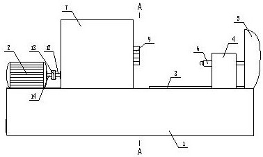
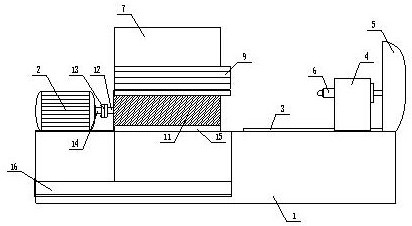
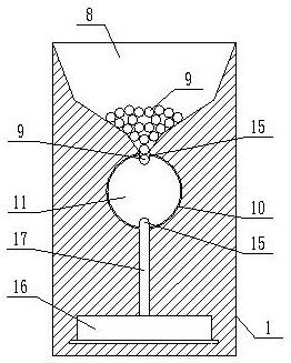
[0033] The present invention is specifically described below in conjunction with accompanying drawing, as Figure 1-8 shown;

[0034] The inventive point of the present application is that a column 7 is also fixedly installed on the workbench, the column is a cuboid, and the top of the column is provided with a hopper 8, and the hopper communicates with the upper surface and the front surface of the column, and inside the hopper Place some metal tubes 9, the metal tubes are parallel to the upper surface of the column, the length of the metal tubes is greater than the length of the hopper, and one end of the metal tubes stretches out from the front surface of the column;

[0035] The inventive point of the present application is also that a through hole 10 is provided at the bottom of the column, the through hole is a cylindrical hole, the through hole communicates with the front and rear surfaces of the column, and the through hole communicates with the feeding port of the hop...


PUM


Abstract

The invention discloses a pipe end opening efficient expanding machine. The machine comprises a workbench, wherein one end of a table top of the workbench is fixedly provided with a motor, the other end of the table top of the workbench is fixedly provided with a guide rail, a sliding seat is mounted on the guide rail, the sliding seat slides along the guide rail under the driving of a hydraulic system, and an impact head is fixedly mounted on the sliding seat; and a stand column is further fixedly mounted on the workbench, the stand column is a cuboid, the upper portion of the stand column isprovided with a hopper, the hopper is in communication with the upper surface and the front surface of the stand column, a plurality of metal pipes are placed in the hopper, and the metal pipes are parallel to the upper surface of the stand column, and the length of each metal pipe is larger than the length of the hopper. The machine has the beneficial effects that work of feeding, opening expanding and finished product collecting can be automatically completed, and the production efficiency is effectively improved.

Description

technical field [0001] The invention relates to the technical field of metal pipe processing, in particular to a high-efficiency flaring machine for pipe fitting ports. Background technique [0002] During the actual use of the metal pipe, according to the use requirements, the port of the metal pipe needs to be flared, and the port of the metal pipe is enlarged by collision through the flaring machine, so as to meet the actual use needs; the existing flaring When the machine is in use, the metal pipe needs to be fixed on the mold by the staff, and then the impact head is driven by the hydraulic system to impact the end port of the metal pipe, and the end port of the metal pipe is enlarged through the impact, and then the staff will finish the process. The flaring metal tube is removed from the mold, and the above actions are repeated; [0003] However, the working method of the above-mentioned belling machine depends on the proficiency and work experience of the staff, so ...

Claims


Application Information

Patent Timeline
Patent Type & Authority Applications(China)
IPC IPC(8): B21D41/02B21D43/00
CPCB21D41/026B21D43/003B21D43/006
Inventor 秦喜顺
Owner 秦喜顺
Learn More