
An optical module fault diagnosis system and method

A fault diagnosis system and fault diagnosis technology, applied in the direction of optical instrument testing, machine/structural component testing, instruments, etc., can solve the problems of limited information, limited storage space of optical modules, lack of storage devices, etc., and achieve abundant resources Effect

Active Publication Date: 2021-04-27
FENGHUO COMM SCI & TECH CO LTD
View PDF10 Cites 0 Cited by
  • Summary
  • Abstract
  • Description
  • Claims
  • Application Information

AI Technical Summary

Problems solved by technology

[0003] However, in practical applications, the fault diagnosis and analysis of optical modules with a rate of 100G and above are difficult to solve related problems in practical applications due to the following difficulties:
[0004] 1. The internal space of the optical module with a rate of 100G and above is tight, coupled with the power consumption limitation, the storage space of the optical module is limited, and the storage device that can be written repeatedly is lacking, which greatly affects the data collection of the optical module during operation. There is not enough data to analyze the fault, so the fault diagnosis cannot be completed effectively;
[0005] 2. Due to the limitation of the external hardware interface of the optical module with a rate of 100G and above (only the MDIO communication interface is external), it is impossible to effectively monitor the internal operation status of the optical module after the optical module leaves the laboratory commissioning environment
Although external devices can obtain information such as the alarm performance of optical modules with a rate of 100G and above in accordance with the standard MSA protocol "CFP MSA Management Interface Specification Version 2.0r09", these information are general information, and the amount of information is limited, so it is impossible to fully feed back the optical module The running status of each internal component cannot report different customized content for different hardware and software architectures;
[0006] 3. Most of the content collected through the MSA protocol is current real-time information, and it is impossible to query the information that has occurred in the past, resulting in some faults with a short duration. Once the fault phenomenon disappears, there is no means to check the state of the fault make inquiries;
[0007] 4. There is a lack of remote fault location means for optical modules with a rate of 100G and above. The current fault location requires debuggers to conduct information inquiries on the project site, and sometimes it is even necessary to remove the optical module from the WDM device with a rate of 100G and above. Only when it is placed on the commissioning platform can the fault be queried and located, which greatly affects the work efficiency

Method used


Image

  • An optical module fault diagnosis system and method
  • An optical module fault diagnosis system and method
  • An optical module fault diagnosis system and method

Examples


Embodiment 1

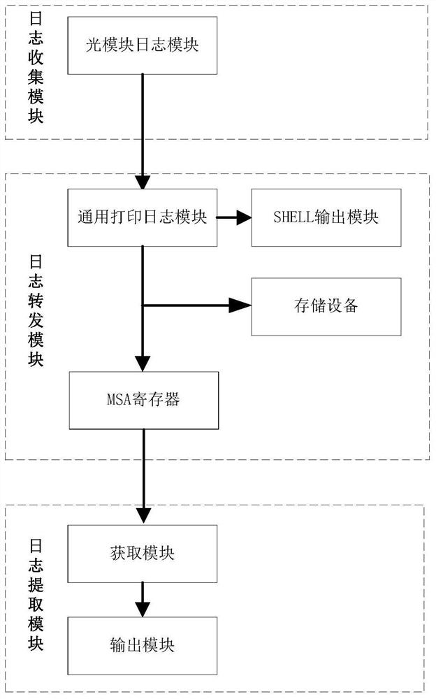
[0042] see figure 1 As shown, the embodiment of the present invention provides an optical module fault diagnosis system, including:

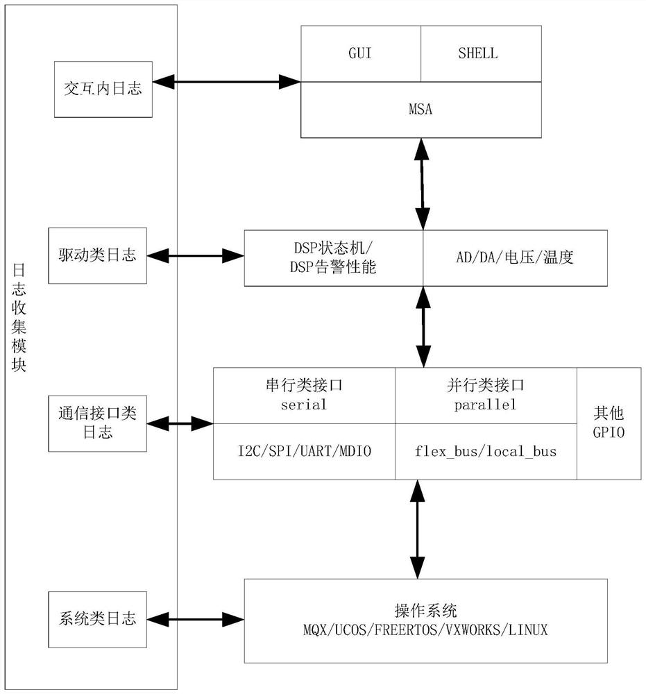
[0043] The log collection module is used to collect log information during the photoelectric signal conversion process of the optical module and provide it to the log forwarding module; the log collection module specifically includes a log collection module, and the log collection module is used to collect log information generated by the optical module. These log information mainly include the hardware running status of the module, the response feedback during the interaction with the outside world, and the running status of the internal software. These log information will be recorded actively (by timing recording) or passively (by responding to commands), and the recorded log information will be processed by the log forwarding function.

[0044]The log forwarding module is used to process the collected log information and forward it to the s...

Embodiment 2

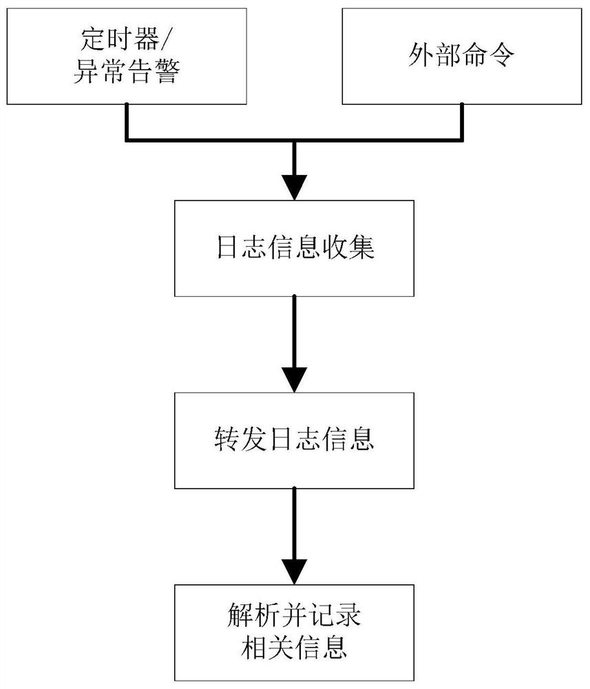
[0052] Such as figure 2 As shown, the present invention also provides an optical module fault diagnosis method using the aforementioned optical module diagnostic device, comprising the following steps:

[0053] S1. Use the log collection module to collect the log information of the photoelectric signal conversion process, such as the operating status parameters of various internal devices, various task stack information at the operating system level, error information on the number of reads and writes at the driver level, and various information on the application level. Business-related alarm performance information, command information at the interaction level, etc., after collecting all the information, pass the log information to the log forwarding module;

[0054] S2. The log forwarding module uses the general printing log module of the optical module to process the collected log information, and forwards it to the serial port of the optical module, the storage device an...

Embodiment 3

[0057] This embodiment provides a method for diagnosing an optical module fault using the aforementioned optical module diagnostic device, which includes not only all the steps in Embodiment 2, but also a process of generating and recording an optical module log before step S1.

[0058] The optical module log supports both internal automatic recording and external trigger recording. In this embodiment, the recording of the optical module log is completed through internal automatic recording. The specific method is: before step S1, set the log collection module to regularly query all hardware and software information and organize and record it as log information. For example, use a timer to trigger regular query, set it to be triggered once an hour, after triggering, the log module will query all hardware and software information and organize records; or set the log collection module to send Relevant information is recorded as log information. For example, when the service is in...


PUM


Abstract

The invention discloses a fault diagnosis system and method for an optical module, and relates to the field of wavelength division equipment. , which is used to forward the log information to the serial port of the optical module, store the log information, and store the log information after packet cutting processing; the log extraction module is used to extract the log information after packet cutting processing, and upload it to the network management system for troubleshooting. The optical module fault diagnosis system and method of the present invention can upload the log to the network management system used with external wavelength division equipment through Ethernet for storage and analysis, and finally complete the fault location, and realize the internal components, packaging space, function and function of the optical module. Troubleshooting functions under severe constraints such as power consumption.

Description

technical field [0001] The invention relates to the field of wavelength division equipment, in particular to an optical module fault diagnosis system and method. Background technique [0002] With the rapid growth of users' demand for optical module links, cloud computing, mobile broadband and IPTV users' requirements for bandwidth are also increasing. In recent years, 100G and above optical modules have developed rapidly in the data center market, gradually replacing the existing 40G links. [0003] However, in practical applications, the fault diagnosis and analysis of optical modules with a rate of 100G and above are difficult to solve related problems in practical applications due to the following difficulties: [0004] 1. The internal space of the optical module with a rate of 100G and above is tight, coupled with the power consumption limitation, the storage space of the optical module is limited, and the storage device that can be written repeatedly is lacking, which...

Claims


Application Information

Patent Timeline
Patent Type & Authority Patents(China)
IPC IPC(8): G01M11/00
CPCG01M11/00
Inventor 肖奇陈登超李强
Owner FENGHUO COMM SCI & TECH CO LTD
Learn More