Light emitting device and method for manufacturing same

a technology of light emitting devices and manufacturing methods, which is applied in the manufacture of semiconductor/solid-state devices, semiconductor devices, electrical devices, etc., can solve the problems of life decline, light emission efficiency decline, etc., and achieve the effect of alleviating the decline in light output efficiency, and easy obtaining a light emitting devi

Inactive Publication Date: 2013-01-10
SHARP KK
View PDF5 Cites 31 Cited by
  • Summary
  • Abstract
  • Description
  • Claims
  • Application Information

AI Technical Summary

Benefits of technology

[0036]As described above, according to the present invention, it is possible to easily obtain a light emitting device and a method for manufacturing the same that are able to alleviate the decline in the light output efficiency caused by the deterioration of the plated layer.
[0037]Besides, according to the present invention, it is possible to easily obtain a light emitting device and a method for manufacturing the same that have an excellent heat radiation characteristic and a high reliability.
[0038]Further, according to the present invention, it is possible to easily obtain a light emitting device and a method for manufacturing the same that are able to increase the yielding.

Problems solved by technology

On the other hand, when driving a light emitting device at a high output, heat generation from the LED element increases, accordingly, thanks to the heat from the LED element, disadvantages such as decline in light emission efficiency, decline in life and the like occur.

Method used


Image

  • Light emitting device and method for manufacturing same
  • Light emitting device and method for manufacturing same
  • Light emitting device and method for manufacturing same

Examples


first embodiment

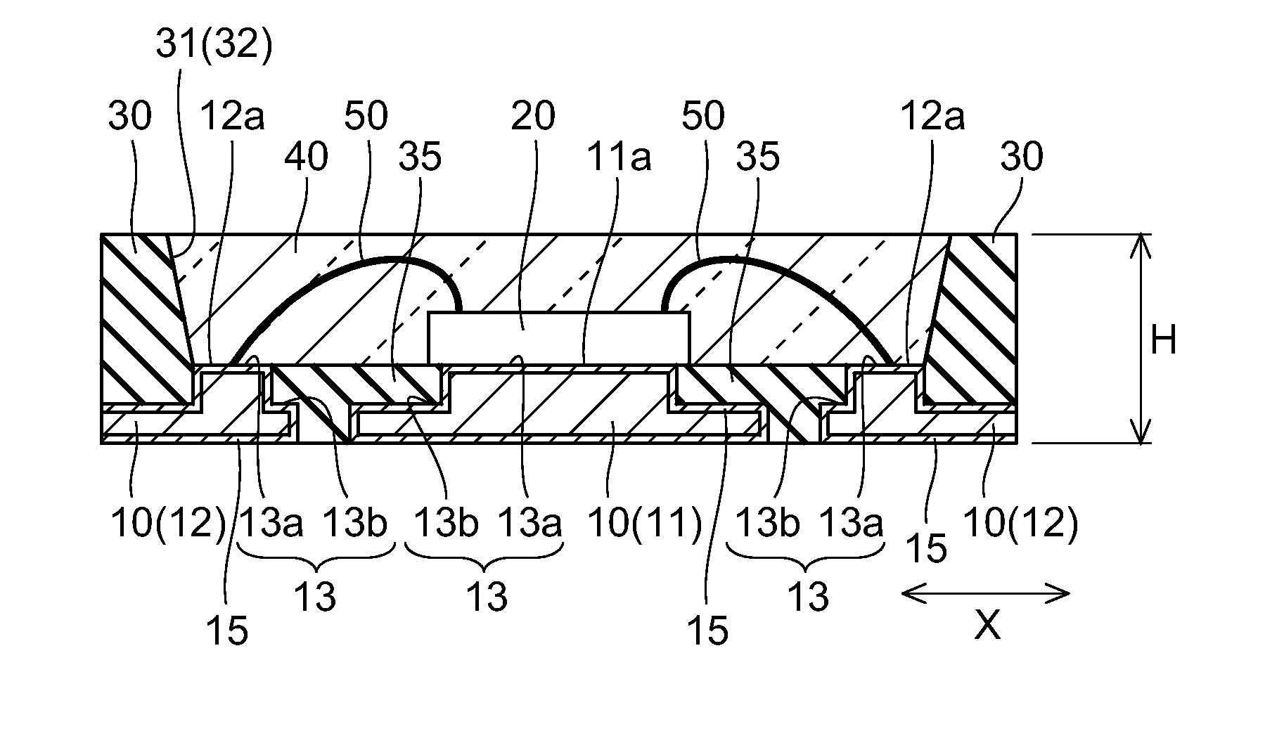
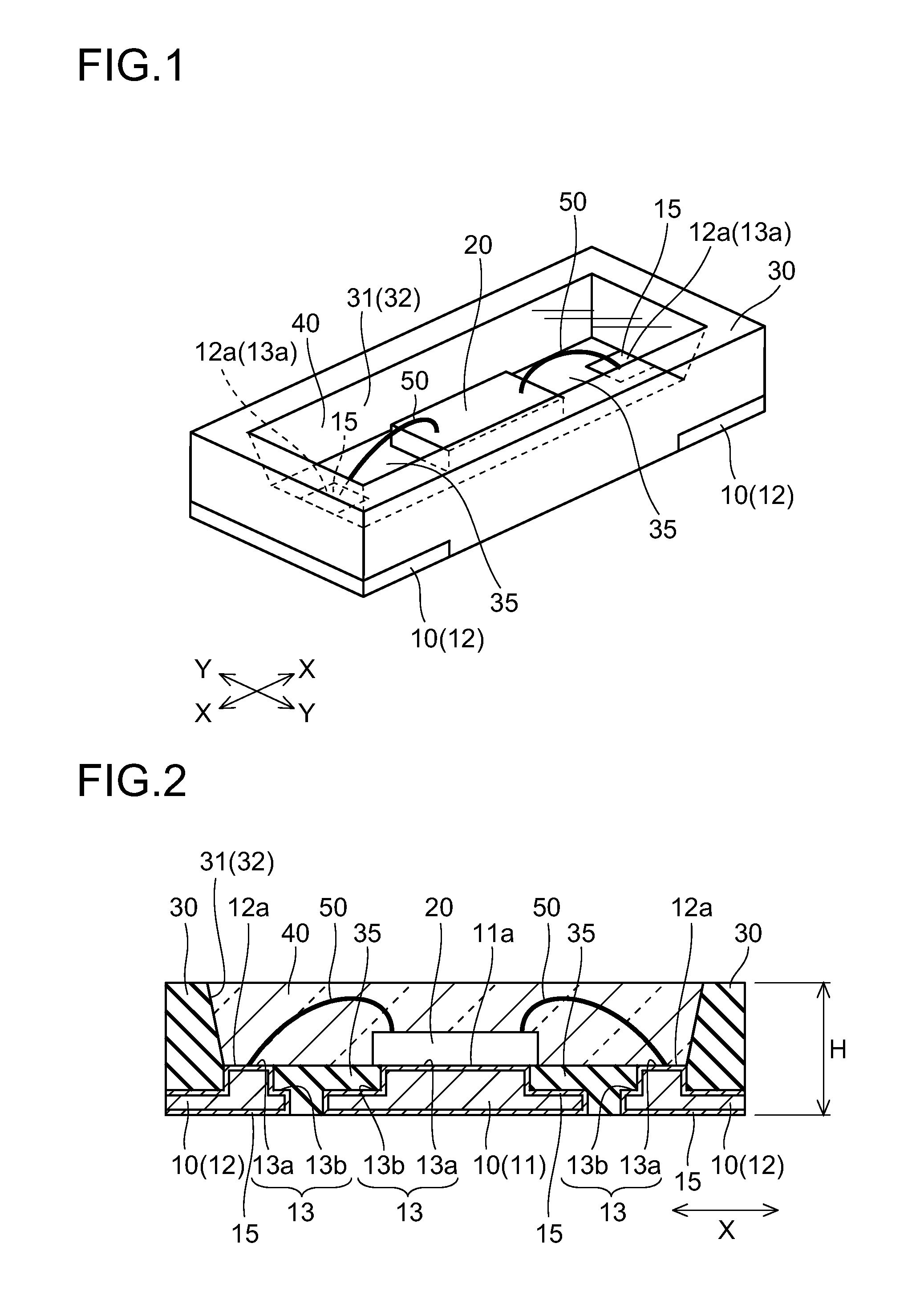
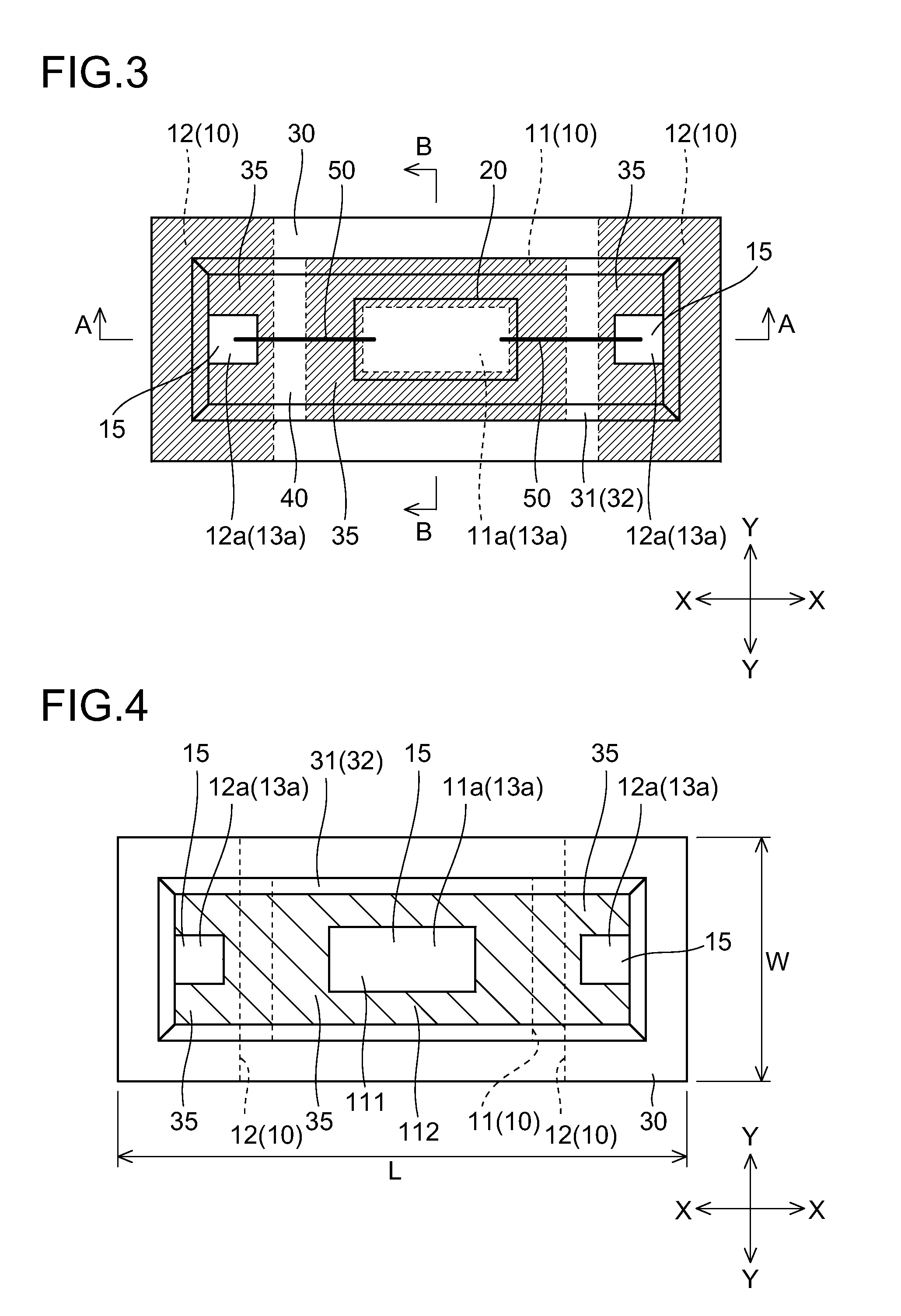
[0064]FIG. 1 is an overall perspective view of a light emitting device according to a first embodiment of the present invention. FIG. 2 is a sectional view of the light emitting device according to the first embodiment of the present invention. FIG. 3 is a plan view of the light emitting device according to the first embodiment of the present invention. FIG. 4 to FIG. 11 are a plan view for describing the light emitting device according to the first embodiment of the present invention. Here, FIG. 4 shows a state in which an LED chip, a wire and a seal member are removed. First, with reference to FIG. 1 to FIG. 11, a structure of the light emitting device according to the first embodiment of the present invention is described.

[0065]The light emitting device according to the first embodiment includes an LED of surface mount type, and is structured to emit white light (pseudo-white light). Specifically, the light emitting device according to the first embodiment, as shown in FIG. 1 to ...

second embodiment

[0112]FIG. 19 is a sectional view according to a second embodiment of the present invention. FIG. 20 and FIG. 21 are plan views of the light emitting device according to the second embodiment of the present invention when seeing from top. FIG. 22 is a plan view of the light emitting device according to the second embodiment of the present invention when seeing from bottom. FIG. 21 shows a state in which the LED chip, the wire and the seal member are removed. Next, with reference to FIG. 19 to FIG. 22, the light emitting device according to the second embodiment of the present invention is described. Here, in each drawing, corresponding constituent elements are indicated by the same reference numbers, whereby double description is skipped.

[0113]The light emitting device according to the second embodiment, as shown in

[0114]FIG. 19 and FIG. 20, is formed to be a surface mount LED of one wire type. Specifically, in the second embodiment, unlike the first embodiment, an LED chip 220, in ...


PUM


Abstract

A light emitting device comprises:
    • a light emitting element (20);
    • a first metal board (11) that includes a mount portion (111) on which the light emitting element (20) is mounted and a reflection portion (112) which is formed outside the mount portion (111) to reflect light from the light emitting element (20);
    • a second metal board (12) that is electrically connected to the light emitting element (20) via a wire (50);
    • a metal plated layer (15) that is formed on a surface of the metal boards (11), (12); and
    • a seal resin (40) that is formed on the metal boards (11), (12) to seal at least the light emitting element (20); wherein
    • at least the reflection portion (112) is provided with a protection layer (35) which is lower than the seal resin (40) in gas permeability, is transparent or has a reflectance near the metal plated layer (15).

Description

TECHNICAL FIELD[0001]The present invention relates to a light emitting device and a method for manufacturing the light emitting device, more particularly, to a light emitting device including a light emitting element and to a method for manufacturing the light emitting device.BACKGROUND ART[0002]A light emitting device using a light emitting diode (LED) has features of low power consumption and long life and the like, and is widely used in various display light sources and the like. Besides, in recent years, a light emitting device using an LED element is finding its wide applications, and needs for a light emitting device which has a high output and a high light emission efficiency are increasing.[0003]On the other hand, when driving a light emitting device at a high output, heat generation from the LED element increases, accordingly, thanks to the heat from the LED element, disadvantages such as decline in light emission efficiency, decline in life and the like occur. Because of t...

Claims


Application Information

Patent Timeline
Patent Type & Authority Applications(United States)
IPC IPC(8): H01L33/60
CPCH01L33/486H01L33/60H01L33/62H01L33/642H01L33/647H01L2224/45144H01L2933/0033H01L2224/48247H01L2924/00
Inventor MEMIDA, YUHICHI
Owner SHARP KK
Why Eureka
Try Eureka