Heat dissipation system for solarlok photovoltaic interconnection system

a photovoltaic array and interconnection system technology, applied in the direction of electrical equipment, lighting and heating equipment, semiconductor devices, etc., can solve the problems of ineffective means for expulsion of heat generated by internal system electronic components, risk of heat rise sufficient to damage enclosures and/or internal components of interconnection systems, etc., to achieve the effect of eliminating heat generated and increasing heat dissipation characteristics

Inactive Publication Date: 2008-05-22
TE CONNECTIVITY CORP
View PDF24 Cites 31 Cited by
  • Summary
  • Abstract
  • Description
  • Claims
  • Application Information

AI Technical Summary

Benefits of technology

[0008]An advantage of the present invention is increased heat dissipation characteristics for connection boxes in a photovoltaic array interconnection system.
[0009]Another advantage is the use of heat pipe technology for eliminating heat generated by interconnection components in a connection box.

Problems solved by technology

Existing photovoltaic (PV) interconnection systems lack efficient means for expelling heat generated from internal system electronic components, e.g., diode assemblies, to the exterior of the interconnection enclosure.
This inability to expel the heat more rapidly causes a risk of heat rise sufficient to damage the enclosure and / or the internal components of the interconnection system.

Method used


Image

  • Heat dissipation system for solarlok photovoltaic interconnection system
  • Heat dissipation system for solarlok photovoltaic interconnection system
  • Heat dissipation system for solarlok photovoltaic interconnection system

Examples


Embodiment Construction

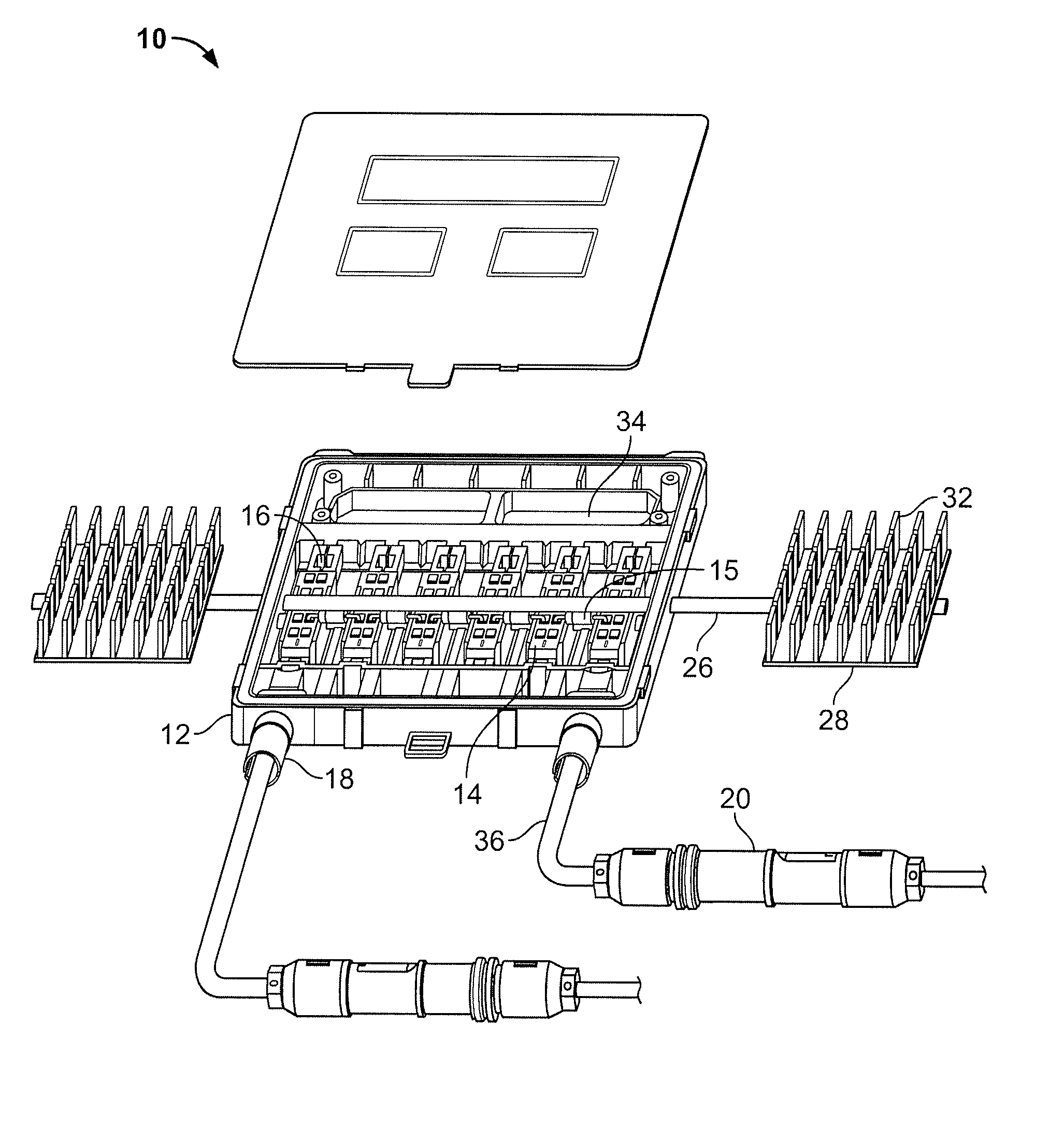
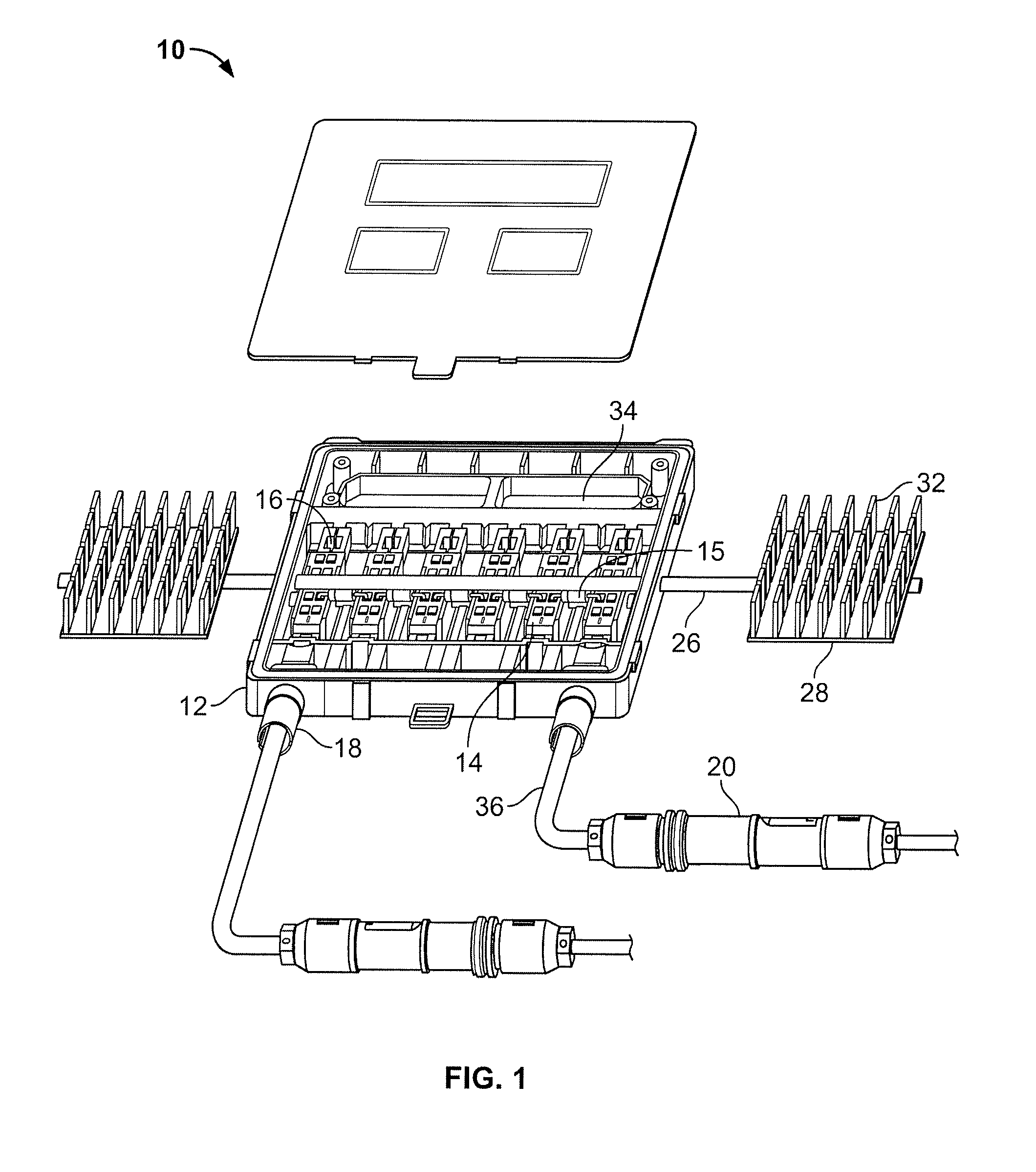
[0014]The heat dissipation system of the present invention is applied to an interconnection system for photovoltaic (PV) arrays, and preferably to a roof mounted PV array, although the PV arrays may be independently mounted on frames, building facades or other configurations.

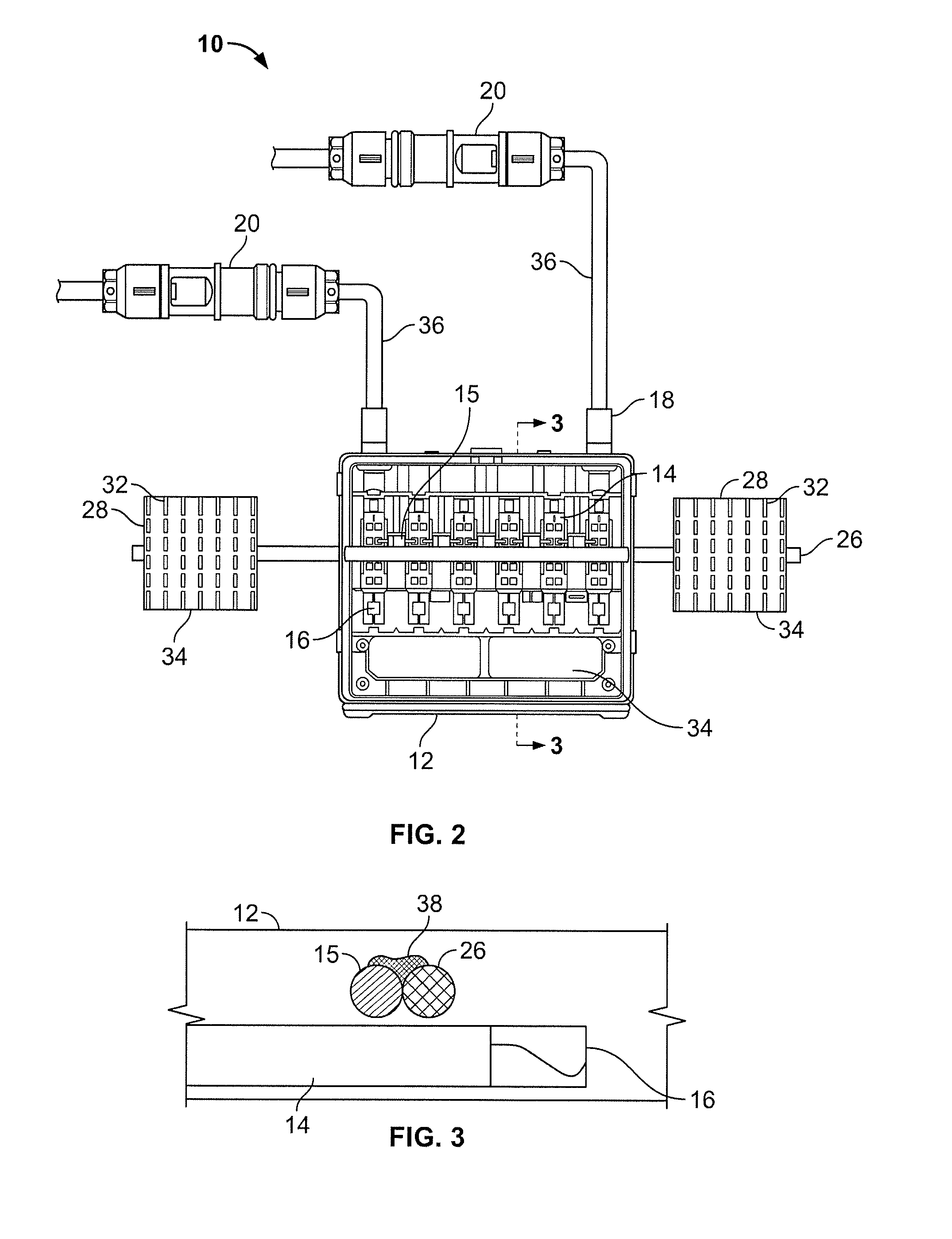
[0015]Referring to FIGS. 1-3, the interconnection system is generally designated as 10. A connection box 12 houses the components of the interconnection system 10, including a series of electrical connectors 14 for connecting conductors of the PV array (not shown). Connectors 16 are mounted to rail assemblies 14. Up to six rail assemblies 14 per connection box 12 is the preferred arrangement, although more than six rail assemblies 14 may be enclosed within a connection box suitable for larger configurations. The rail assemblies 14 provide mechanical support for the connectors 14. Connectors 16 are electrically isolated from the diode assemblies 15.

[0016]The connection box 12 has cable couplers 18, and an apertur...


PUM


Abstract

A heat dissipation system for a photovoltaic array (PV) interconnection system includes an enclosure containing one or more diode elements. A heat pipe system has heat sinks attached to one or both ends. The heat pipe passes through the enclosure in thermal contact with the diode assemblies. Cooling fins are arranged on the heat sink such that heat from the heat pipe is conducted into the fin and the fin dissipates the heat to the ambient atmosphere outside of the enclosure to cool the components within the enclosure.

Description

FIELD OF THE INVENTION[0001]The present invention is directed to a heat dissipation system for a photovoltaic array interconnection system, and more particularly to a connection box having a heat pipe for dissipating heat generated by internal components of the photovoltaic interconnection system.BACKGROUND OF THE INVENTION[0002]Existing photovoltaic (PV) interconnection systems lack efficient means for expelling heat generated from internal system electronic components, e.g., diode assemblies, to the exterior of the interconnection enclosure. This inability to expel the heat more rapidly causes a risk of heat rise sufficient to damage the enclosure and / or the internal components of the interconnection system.[0003]Heat pipes are devices that are well known, for example, for use in space technology, dehumidification and air conditioning applications, and laptop CPU cooling systems. “Heat pipe” is a term that refers to a closed pipe containing a working fluid such as water which is p...

Claims


Application Information

Patent Timeline
Patent Type & Authority Applications(United States)
IPC IPC(8): F28D15/02
CPCF28D15/02H01L2924/0002H02S40/345H02S40/34H01L2924/00Y02E10/50
Inventor DUESTERHOEFT, SCOTT STEPHEN
Owner TE CONNECTIVITY CORP
Why Eureka
Try Eureka