Method for quickly positioning optical fiber breakpoint

A breakpoint and optical fiber technology, applied in electromagnetic wave transmission systems, electrical components, transmission systems, etc., can solve the problems of the length of one side of the optical cable joint box, the difficulty of determining the breakpoint and the fiber port, and the difficulty of determining the location of the breakpoint, etc. Achieve the effects of shortening troubleshooting time, improving breakpoint location efficiency, and improving maintenance efficiency

Active Publication Date: 2019-11-19
王新凤
View PDF5 Cites 6 Cited by
  • Summary
  • Abstract
  • Description
  • Claims
  • Application Information

AI Technical Summary

Problems solved by technology

However, in the actual operation process, it is difficult to determine the breakpoint position only by relying on this information, and the operation is difficult
When the optical fiber is laid, it will be laid in pipes or overhead, and there will be natural bending of the optical cable during the laying process, and there will be a length of one-sided coil in the optical cable splice box, which will lead to the distance between the breakpoint and the optical fiber port when searching for the line. Known but still difficult to locate, especially when the cable is sound on the outside but the fiber inside is broken

Method used


Image

  • Method for quickly positioning optical fiber breakpoint
  • Method for quickly positioning optical fiber breakpoint
  • Method for quickly positioning optical fiber breakpoint

Examples


Embodiment Construction

[0018] The present invention will be described in further detail below in conjunction with the accompanying drawings and specific embodiments.

[0019] A method for rapidly locating an optical fiber breakpoint, specifically comprising the following steps:

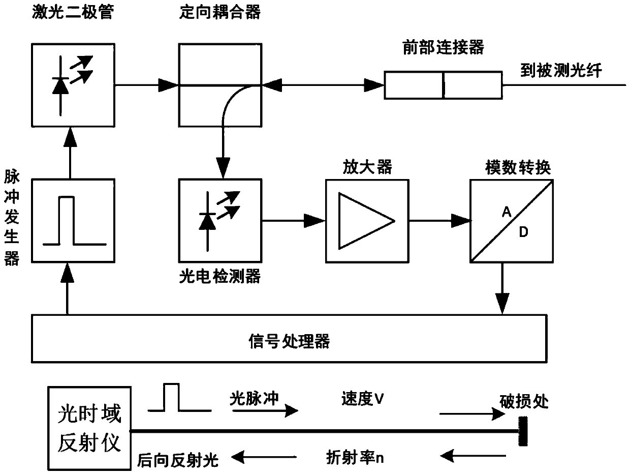
[0020] 1) When a breakpoint occurs in the optical cable, first use an optical time domain reflectometer to measure the distance between the breakpoint of the optical fiber and the port, and use the distance value as a reference value;

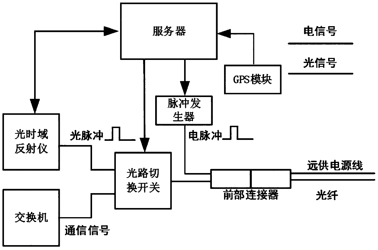
[0021] 2) The server controls the second pulse generator to generate electric pulse signals, and the pulse generator is connected to the remote power supply line of the optical cable. The conductivity of the remote power supply line will make the voltage value of the electric pulse signal be transmitted to each of the remote power supply lines. location, when the voltage of the remote power supply line changes, an induced electromagnetic field will be generated;

[0022] 3) When the remote ...


PUM


Abstract

The invention discloses a method for quickly positioning an optical fiber breakpoint, and the method specifically comprises the following steps: 1), measuring the distance between the optical fiber breakpoint and a port through employing an optical time domain reflectometer, and enabling the distance value to serve as a reference value; 2), controlling a second pulse generator to generate an electric pulse signal by a server; 3), capturing voltage change by utilizing electromagnetic induction equipment, and calculating the length from the point to the end point of the optical fiber by utilizing the time difference of electric signal transmission; 4), using the GPS to time by the server; 5), eliminating the deviation between the server and the GPS receiving device of the pulse induction measuring device; and 6), when the distance value measured by the electromagnetic induction equipment is the same as the distance value measured by the optical time domain reflectometer, determining thepoint as the optical cable breakpoint. The method has the advantage that the position of the breakpoint can be quickly found. The method is reasonable and effective, can effectively improve the optical fiber breakpoint positioning efficiency, shortens the troubleshooting time, improves the maintenance efficiency, and is high in application value.

Description

technical field [0001] The invention relates to a method for quickly locating a breakpoint of an optical fiber. Background technique [0002] At present, optical fiber communication has become the main way of information transmission and is widely used all over the world. As the length of optical fiber is increasing, the difficulty of maintenance is also increasing, and the economic loss caused by the interruption of optical fiber communication is also increasing. Factors such as engineering construction, environmental changes, and man-made damage will cause damage to the optical fiber, so it is of great significance to quickly locate the breakpoint of the optical fiber. Optical fiber communication failures mainly include fiber cut obstacles and attenuation-increasing obstacles at a certain point of the optical fiber link. The former is blocked by data, while the latter increases the attenuation of communication signals, reduces communication distance, and increases the bit ...

Claims


Application Information

Patent Timeline
Patent Type & Authority Applications(China)
IPC IPC(8): H04B10/071
CPCH04B10/071
Inventor 王新凤
Owner 王新凤
Why Eureka
Try Eureka