Engine exhaust pipe core pulling mechanism

A core-pulling mechanism and exhaust pipe technology, applied in the field of molds, can solve the problems of difficult and inconvenient core-pulling

Active Publication Date: 2021-07-02
NINGBO FANGZHENG TOOL
View PDF0 Cites 1 Cited by
  • Summary
  • Abstract
  • Description
  • Claims
  • Application Information

AI Technical Summary

Problems solved by technology

The shape of the engine exhaust pipe channel is arc-shaped. When forming, it is necessary to use the core-pulling mechanism to pull the engine exhaust pipe. According to the existing technology, the engine exhaust pipe is core-pulled by using an ordinary arc core-pulling mechanism. , core pulling is inconvenient, core pulling is difficult

Method used


Image

  • Engine exhaust pipe core pulling mechanism
  • Engine exhaust pipe core pulling mechanism
  • Engine exhaust pipe core pulling mechanism

Examples


Embodiment Construction

[0028] The present invention will be further described below with reference to the accompanying drawings and specific embodiments.

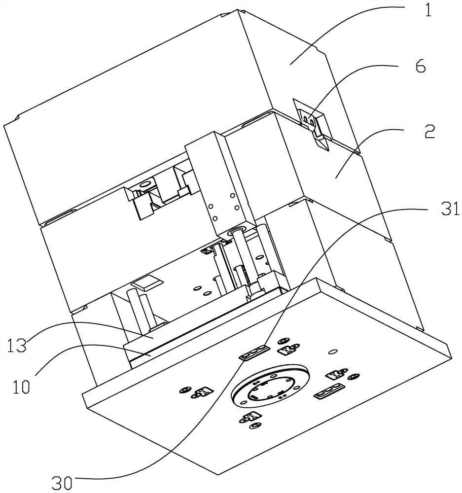
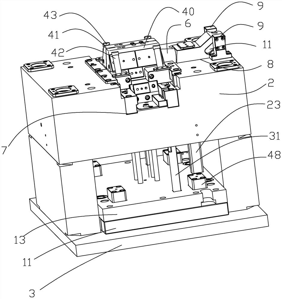
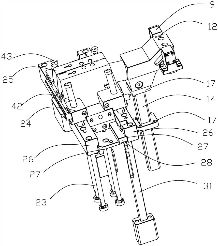
[0029] As shown in the figure, the present invention provides an engine exhaust pipe core pulling mechanism, which includes an upper template 1, a lower template 2, a mold foot 3, a product 4, a thimble plate 10 and a mold core for molding the product 4. The said The upper die plate 1 is located on the upper surface of the lower die plate 2, the lower die plate 2 is located between the upper die plate 1 and the die foot 3, and the ejector plate 10 is slidably fitted between the die foot 3 and the lower die plate 2. The mold core includes a first mold core 5 for molding the lower end of the product 4 and a second mold core 6 for molding the upper end of the product 4. The first mold core 5 corresponds to the linear core pulling of a small part of the product 4, so The second mold core 6 corresponds to most of the arc core pulling of the product 4,...


PUM


Abstract

The invention discloses a core-pulling mechanism for an engine exhaust pipe, comprising an upper template, a lower template, a mold foot, a product, a thimble plate and a mold core for forming a product, the upper template is located on the upper surface of the lower template, and the The lower template is located between the upper template and the die foot, the ejector plate is slidingly fitted between the die foot and the lower template, and the mold core includes a first mold core for forming the lower end of the product and a mold core for forming The second mold core in the upper end of the product, the first mold core corresponds to the linear core pulling of a small part of the product, the second mold core corresponds to the arc core pulling of most of the product, and the upper surface of the lower template is along the The width direction of the lower template is provided with a first opening groove, and the upper surface of the lower template is provided with a second opening groove along the length direction of the lower template, and one end of the second opening groove communicates with the first opening groove. The present invention provides a The core-pulling mechanism of the engine exhaust pipe is convenient and easy to pull the core.

Description

technical field [0001] The invention relates to the field of molds, in particular to a core-pulling mechanism for an engine exhaust pipe. Background technique [0002] With the development of science and technology, automobiles have gradually become a common means of transportation for people. The engine exhaust pipe is one of the components of the automobile. The material of the engine exhaust pipe is soft rubber, and the engine exhaust pipe is formed by a mold. The shape of the engine exhaust pipe channel is arc-shaped. When forming, the engine exhaust pipe needs to be core-pulled by a core-pulling mechanism. According to the prior art, the engine exhaust pipe is core-pulled by using an ordinary arc core-pulling mechanism. , it is inconvenient to pull the core, and it is difficult to pull the core. SUMMARY OF THE INVENTION [0003] The technical problem to be solved by the present invention is to overcome the above defects of the prior art, and to provide an engine exha...

Claims


Application Information

Patent Timeline
Patent Type & Authority Patents(China)
IPC IPC(8): B29C45/26B29C45/33B29C45/40B29C45/44
CPCB29C45/2614B29C45/33B29C45/4005B29C45/4407B29C2045/338
Inventor 刘朝兴康庆文方永杰薛东波娄群全胡天天李邦刘虹
Owner NINGBO FANGZHENG TOOL
Why Eureka
Try Eureka