Crushing device for natural gas hydrate exploitation

A crushing device and hydrate technology, which is applied to the driving device for drilling in the borehole, production fluid, earthwork drilling and production, etc., can solve the problems of low heat utilization efficiency, slow action of natural gas hydrate layer, and expensive chemical reagents, etc. Achieve high crushing efficiency, improve support reliability and stability, and expand the area

Inactive Publication Date: 2019-11-22
CHINA UNIV OF PETROLEUM (EAST CHINA)
View PDF7 Cites 6 Cited by
  • Summary
  • Abstract
  • Description
  • Claims
  • Application Information

AI Technical Summary

Problems solved by technology

The traditional methods of exploiting natural gas hydrate include: (1) Pyrolysis method: the pyrolysis method is to directly heat the natural gas hydrate layer, so that the temperature of the natural gas hydrate layer exceeds its equilibrium temperature, thereby promoting the decomposition of natural gas hydrate into water and Natural gas extraction method, but the heat utilization efficiency of this method is low, and the leaked methane can cause a greenhouse effect ten times more serious than carbon dioxide; (2) Depressurization method: The depressurization method promotes the decomposition of natural gas hydrate by reducing the pressure However, it is only economically feasible when the natural gas hydrate reservoir is located near the temperature-pressure equilibrium boundary; (3) chemical reagent injection production method: by injecting certain chemical reagents into the natural gas hydrate layer to destroy the natural gas hydrate The phase equilibrium condition of the reservoir promotes the decomposition of gas hydrate, but the chemical reagents required for it are expensive, the effect on the gas hydrate layer is slow, and it will also bring some environmental problems

Method used


Image

  • Crushing device for natural gas hydrate exploitation
  • Crushing device for natural gas hydrate exploitation
  • Crushing device for natural gas hydrate exploitation

Examples


Embodiment Construction

[0037] The technical solutions in the embodiments of the present invention will be clearly and completely described below in conjunction with the accompanying drawings in the embodiments of the present invention. Obviously, the described embodiments are only a part of the embodiments of the present invention, rather than all the embodiments. Based on the embodiments of the present invention, all other embodiments obtained by those of ordinary skill in the art without creative work shall fall within the protection scope of the present invention.

[0038] The present invention will be further explained below in conjunction with the drawings and examples:

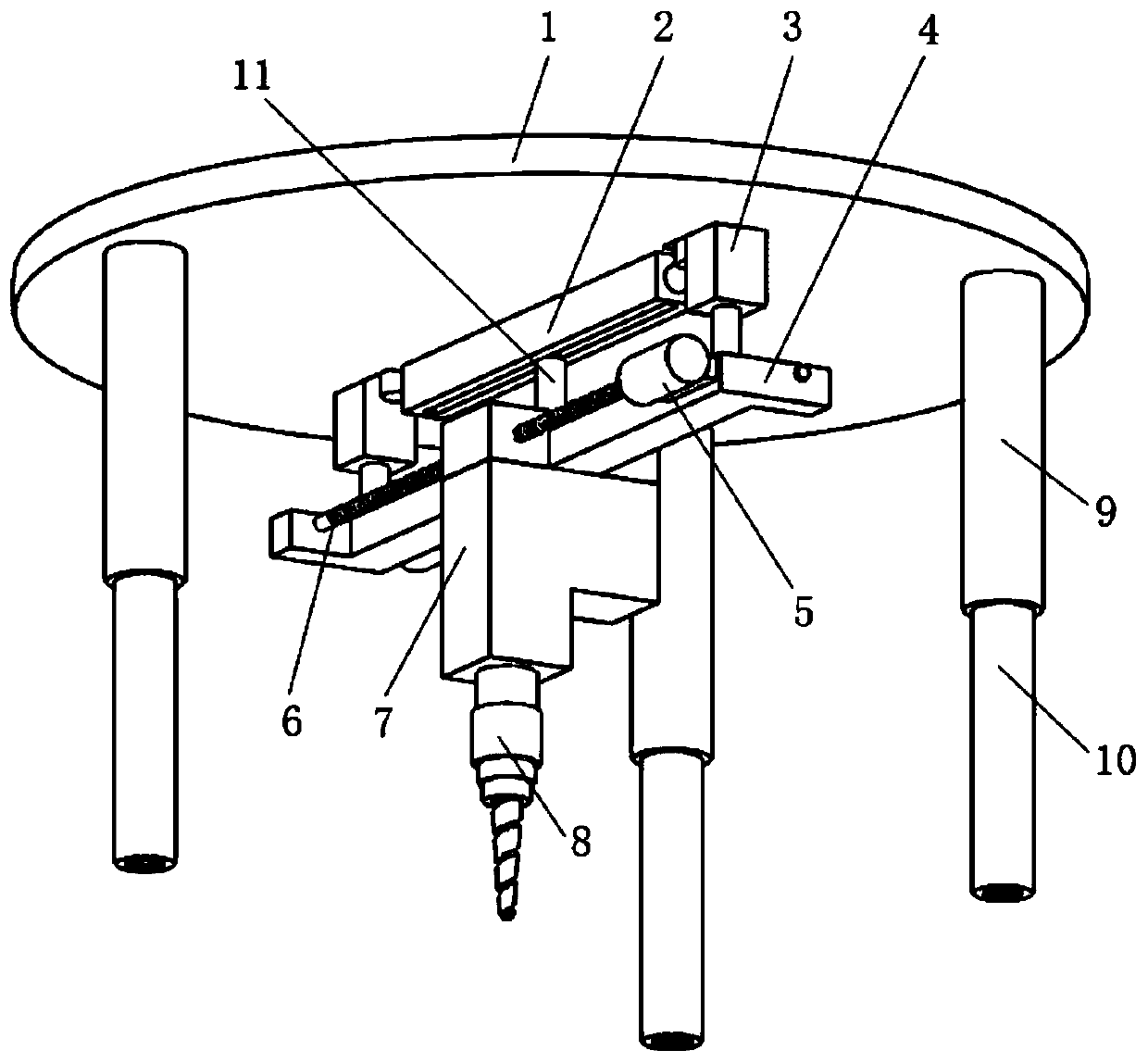
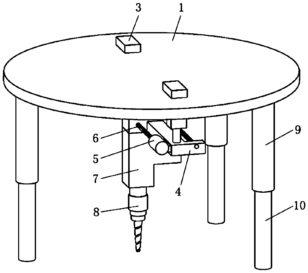
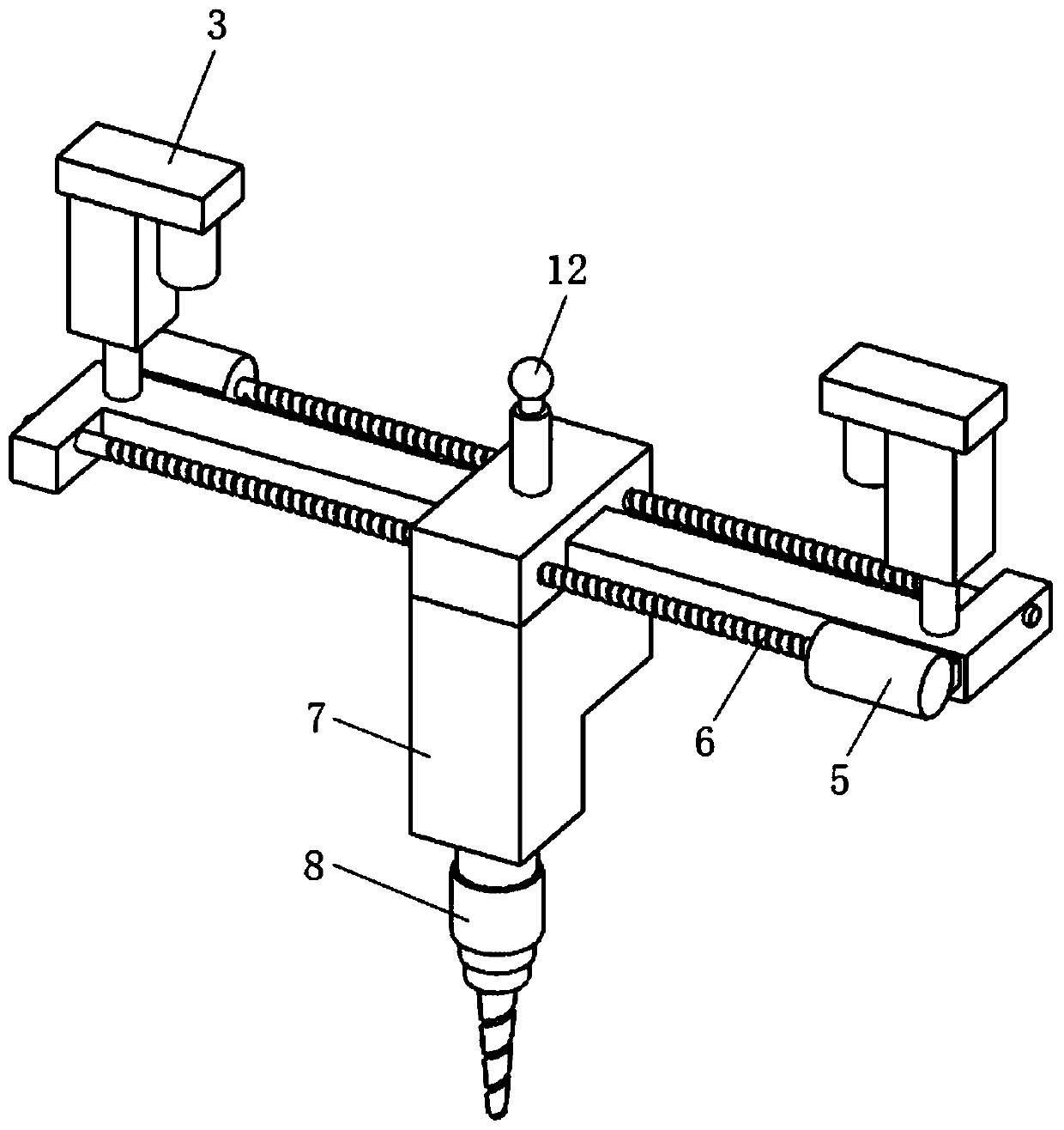
[0039] In the embodiment of the present invention, a natural gas hydrate opening adopts a crushing device, and an electric push rod pushes the ice nail to rotate in the lower support leg while moving downward to drive the main body of the ice nail to rotate into the natural gas hydrate layer and into the natural gas hydrate layer T...


PUM


Abstract

The invention relates to a crushing device, in particular to a crushing device for natural gas hydrate exploitation, and belongs to the technical field of natural gas hydrate exploitation. According to the crushing device, the ice piton body of an ice piton is pushed through an electric push rod to be screwed in a natural gas hydrate layer so as to increase the support reliability and stability ofthe whole device, so that the weight of the whole device is not too large; when a spiral hammer head rotates, the natural gas hydrate layer is impacted downwards, the lower end of the conical sectionof the spiral hammer head is firstly hammered in the natural gas hydrate layer, and then the part, the diameter of which is bigger and bigger, enters the natural gas hydrate layer; the natural gas hydrate layer, around the conical section, with cracks is extruded again to enlarge the areas of the cracks of the natural gas hydrate layer; the downward impact of the spiral hammer head plays a role in vibrating the natural gas hydrate layer, so that the crushing efficiency is relatively high; and in the process that a shell and a spiral ice hammering mechanism horizontally move along a long spiral rod, the spiral hammer head is capable of crushing the natural gas hydrate layer in a large range along with the movement of the shell, so that the crushing range is wide.

Description

Technical field [0001] The invention relates to a crushing device, in particular to a crushing device for natural gas hydrate exploitation, belonging to the technical field of natural gas hydrate exploitation. Background technique [0002] Natural gas hydrate can be combustible ice. It is distributed in deep-sea sediments or permafrost on land. It is formed by natural gas and water under high pressure and low temperature conditions. It can be converted into 164 cubic meters of combustible ice. Meters of natural gas and 0.8 cubic meters of water, and there is almost no residue after the combustion of natural gas hydrate, and the pollution is much smaller than that of coal, oil, and natural gas. Therefore, the exploitation of natural gas hydrate is very important. The traditional methods of mining natural gas hydrates include: (1) Pyrolysis method: The pyrolysis method directly heats the natural gas hydrate layer so that the temperature of the natural gas hydrate layer exceeds its ...

Claims


Application Information

Patent Timeline
Patent Type & Authority Applications(China)
IPC IPC(8): E21B43/01E21B4/12E21B4/16
CPCE21B4/12E21B4/16E21B43/01
Inventor 张辛王旱祥兰文剑刘延鑫
Owner CHINA UNIV OF PETROLEUM (EAST CHINA)
Why Eureka
Try Eureka