A crushing device for natural gas hydrate development

A technology for crushing device and hydrate, which is applied in the drilling driving device, production fluid, earth-moving drilling and other directions in the wellbore, can solve the problems of slow action of natural gas hydrate layer, high cost of chemical reagents, low heat utilization efficiency, etc. Achieve the effect of improving support reliability and stability, expanding area and high crushing efficiency

Inactive Publication Date: 2021-04-09
CHINA UNIV OF PETROLEUM (EAST CHINA)
View PDF7 Cites 0 Cited by
  • Summary
  • Abstract
  • Description
  • Claims
  • Application Information

AI Technical Summary

Problems solved by technology

The traditional methods of exploiting natural gas hydrate include: (1) Pyrolysis method: the pyrolysis method is to directly heat the natural gas hydrate layer, so that the temperature of the natural gas hydrate layer exceeds its equilibrium temperature, thereby promoting the decomposition of natural gas hydrate into water and Natural gas extraction method, but the heat utilization efficiency of this method is low, and the leaked methane can cause a greenhouse effect ten times more serious than carbon dioxide; (2) Depressurization method: The depressurization method promotes the decomposition of natural gas hydrate by reducing the pressure However, it is only economically feasible when the natural gas hydrate reservoir is located near the temperature-pressure equilibrium boundary; (3) chemical reagent injection production method: by injecting certain chemical reagents into the natural gas hydrate layer to destroy the natural gas hydrate The phase equilibrium condition of the reservoir promotes the decomposition of gas hydrate, but the chemical reagents required for it are expensive, the effect on the gas hydrate layer is slow, and it will also bring some environmental problems

Method used


Image

  • A crushing device for natural gas hydrate development
  • A crushing device for natural gas hydrate development
  • A crushing device for natural gas hydrate development

Examples


Embodiment Construction

[0037] The following will clearly and completely describe the technical solutions in the embodiments of the present invention with reference to the accompanying drawings in the embodiments of the present invention. Obviously, the described embodiments are only some, not all, embodiments of the present invention. Based on the embodiments of the present invention, all other embodiments obtained by persons of ordinary skill in the art without making creative efforts belong to the protection scope of the present invention.

[0038] Below in conjunction with accompanying drawing and example the present invention will be further described:

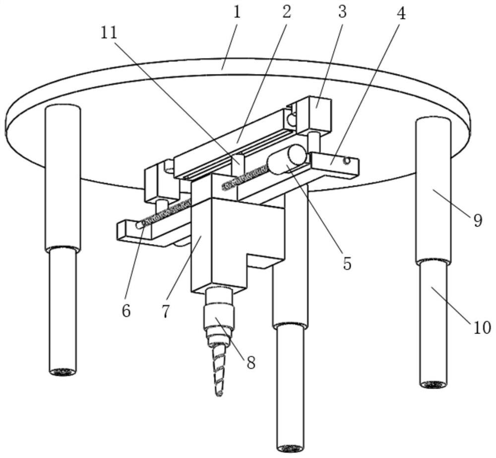
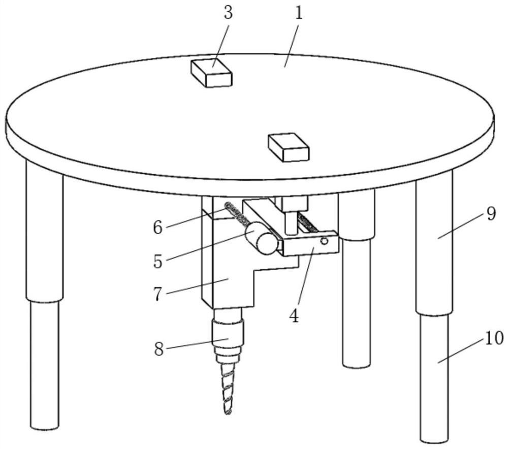
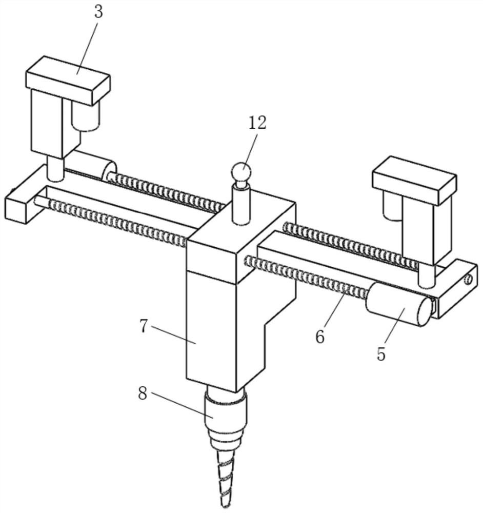
[0039] A crushing device for natural gas hydrate exploitation according to the embodiment of the present invention, the electric push rod pushes the ice nail to rotate in the lower support leg and at the same time moves downward to drive the main body of the ice nail to screw into the natural gas hydrate layer and screw into the natural gas hydra...


PUM


Abstract

The invention relates to a crushing device, in particular to a crushing device for natural gas hydrate exploitation, which belongs to the technical field of natural gas hydrate exploitation. The main body of the ice nail is driven by the electric push rod to screw into the natural gas hydrate layer, which increases the support reliability and stability of the whole device, so that the weight of the whole device does not need to be too large; the screw hammer head rotates and impacts the natural gas hydrate downward at the same time The lower end of the conical section of the spiral hammer first hammers into the natural gas hydrate layer, and then the part with larger and larger diameters enters the natural gas hydrate layer, and squeezes the cracked natural gas hydrate layer around the conical section again , expand the crack area of ​​the natural gas hydrate layer, and the downward impact of the screw hammer will vibrate the natural gas hydrate layer, and the crushing efficiency is high; when the casing and the screw hammer ice mechanism move horizontally along the long screw rod, the screw hammer will With the movement of the shell, it can break a larger range of natural gas hydrate layers, and the breaking range is wide.

Description

technical field [0001] The invention relates to a crushing device, in particular to a crushing device for natural gas hydrate exploitation, which belongs to the technical field of natural gas hydrate exploitation. Background technique [0002] Natural gas hydrate is combustible ice, which is distributed in deep sea sediments or permafrost on land. It is an ice-like crystalline substance formed by natural gas and water under high pressure and low temperature conditions. 1 cubic meter of combustible ice can be converted into 164 cubic meters meters of natural gas and 0.8 cubic meters of water, and the combustion of natural gas hydrate hardly produces any residue, and the pollution is much smaller than that of coal, oil, and natural gas, so the exploitation of natural gas hydrate is very important. The traditional methods of exploiting natural gas hydrate include: (1) Pyrolysis method: the pyrolysis method is to directly heat the natural gas hydrate layer, so that the temperatu...

Claims


Application Information

Patent Timeline
Patent Type & Authority Patents(China)
IPC IPC(8): E21B43/01E21B4/12E21B4/16
CPCE21B4/12E21B4/16E21B43/01
Inventor 张辛王旱祥兰文剑刘延鑫
Owner CHINA UNIV OF PETROLEUM (EAST CHINA)
Why Eureka
Try Eureka