
Gas turbine engine

一种气体涡轮、引擎的技术,应用在燃气轮机装置、涡轮/推进装置的进气口、喷气推进装置等方向,能够解决噪音、短舱热损害、增加气体涡轮引擎核心重量等问题

Active Publication Date: 2019-11-22
ROLLS ROYCE PLC
View PDF9 Cites 0 Cited by
  • Summary
  • Abstract
  • Description
  • Claims
  • Application Information

AI Technical Summary

Problems solved by technology

Such arrangements require reinforced orifices in the outer casing, seals and sealing bands, all of which add weight to the gas turbine engine core
Also, venting the compressor bleed air into the bypass line may risk thermal damage to the nacelle and may create additional noise

Method used


Image

  • Gas turbine engine
  • Gas turbine engine
  • Gas turbine engine

Examples


Embodiment Construction

[0040] As noted elsewhere herein, the present disclosure relates to gas turbine engines. Such gas turbine engines may include an engine core including a turbine, a combustor, a compressor, and a mandrel connecting the turbine to the compressor. Such gas turbine engines may include a fan (with fan blades) located upstream of the engine core.

[0041] The arrangement of the present disclosure may be particularly, but not exclusively, beneficial for fans driven via a gearbox. Accordingly, the gas turbine engine may include a gearbox receiving input from the spindle and driving output to the fan to drive the fan at a lower rotational speed than the spindle. The input to the gearbox may come directly from the spindle or indirectly from the spindle, for example via spur shafts and / or gears. The mandrel may rigidly connect the turbine and compressor so that the turbine and compressor rotate at the same speed (where the fan rotates at a slower speed).

[0042] A gas turbine engine ...


PUM


Abstract

The invention relates to a gas turbine engine. The gas turbine engine comprises an engine core comprising a compressor; a compressor bleed valve in communication with the compressor and configured torelease bleed air from the compressor; at least one component provided at the inlet of the engine core having a de-icing conduit, configured to receive the bleed air; and a flow controller, configuredto provide bleed air to the de-icing conduit of the at least one component in response to either or both of a requirement to de-ice the component and a requirement to release bleed air from the compressor to optimize operation of the core. The flow controller is configured to provide a first mass flow rate of bleed air when the bleed air is provided in response to a requirement to de-ice the component and a second mass flow rate of bleed air, different from the first mass flow rate, when the bleed air is provided in response to a requirement to release bleed air from the compressor to optimize operation of the core, and to provide the higher of the first and second mass flow rates of bleed air when the bleed air is required both for de-icing the component and to optimize operation of thecore.

Description

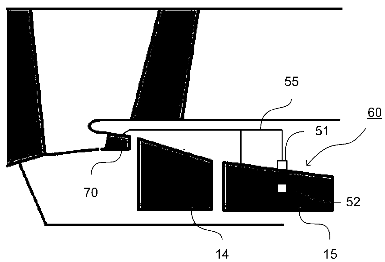
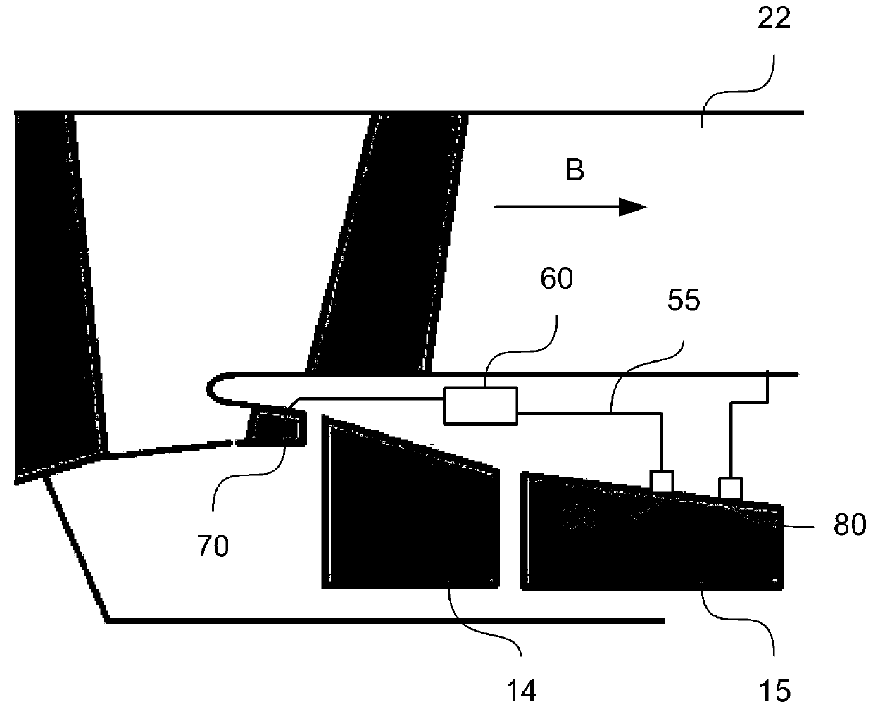
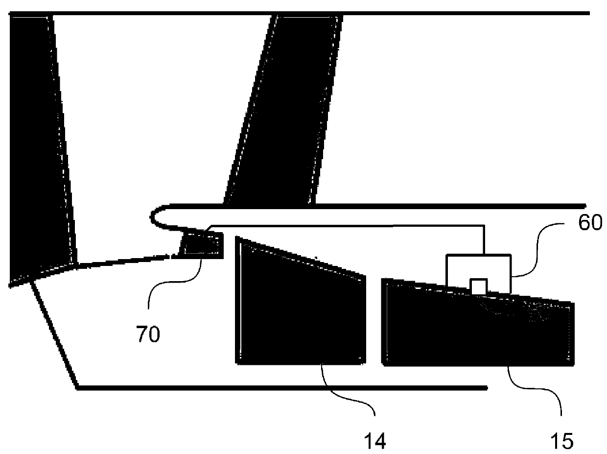
technical field [0001] The present disclosure relates to gas turbine engines, and in particular to gas turbine engines including a compressor bleed air valve for releasing bleed air from a compressor. Background technique [0002] Gas turbine engines may require compressor bleed valves to relieve pressure from compressor stages within the core of the gas turbine engine. In some gas turbine engines, compressor bleed air is discharged through an outlet in the outer casing of the core into the engine's bypass duct. In a typical arrangement, the compressor induction valve is located in the compressor casing (or inner core casing) and is piped to an orifice in the outer casing. Such arrangements require reinforced apertures, seals and sealing bands in the outer casing, all of which add weight to the gas turbine engine core. Also, venting the compressor bleed air into the bypass line may risk thermal damage to the nacelle and may generate additional noise. [0003] It is an obj...

Claims


Application Information

Patent Timeline
Patent Type & Authority Applications(China)
IPC IPC(8): F02C7/04F02C7/057
CPCF02C7/04F02C7/057F05D2260/607F05D2260/606F02C6/08F02C9/18F02C7/047F05D2270/10F05D2270/101B64D2033/0233F01D25/02F05D2270/303
Inventor D.P.斯科森S.P.库尔维克S.佩雷拉E.J.斯帕尔顿
Owner ROLLS ROYCE PLC
Features
  • Generate Ideas
  • Intellectual Property
  • Life Sciences
  • Materials
  • Tech Scout
  • Unparalleled Data Quality
  • Higher Quality Content
  • 60% Fewer Hallucinations
Learn More