Apparatus for aircraft with high peak power equipment

a technology of aircraft and equipment, applied in the field of electric power systems, can solve the problems of affecting the normal system operation, requiring power extraction beyond the capability of equipment, and weight penalty

Active Publication Date: 2013-05-09
NORTHROP GRUMMAN SYST CORP
View PDF6 Cites 43 Cited by
  • Summary
  • Abstract
  • Description
  • Claims
  • Application Information

AI Technical Summary

Problems solved by technology

Such equipment requires power extraction beyond the capability of state-of-the-art (SOA) engine high pressure spool driven generators.
Discharging high peak power may affect the normal system operation.
If the...

Method used


Image

  • Apparatus for aircraft with high peak power equipment
  • Apparatus for aircraft with high peak power equipment
  • Apparatus for aircraft with high peak power equipment

Examples


Embodiment Construction

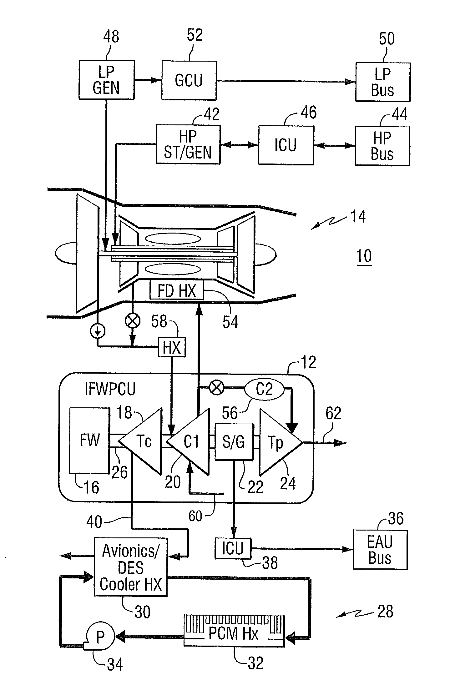
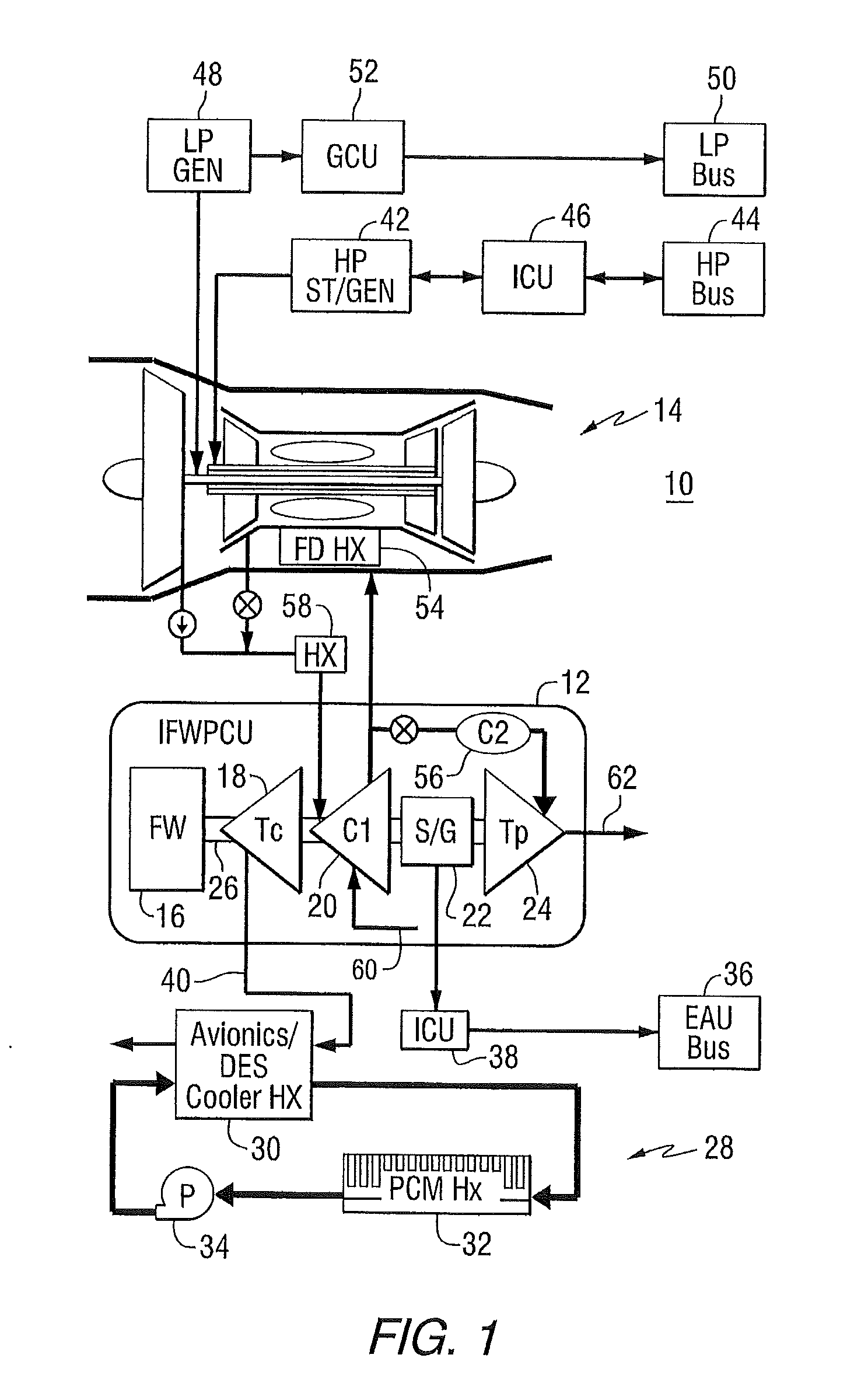
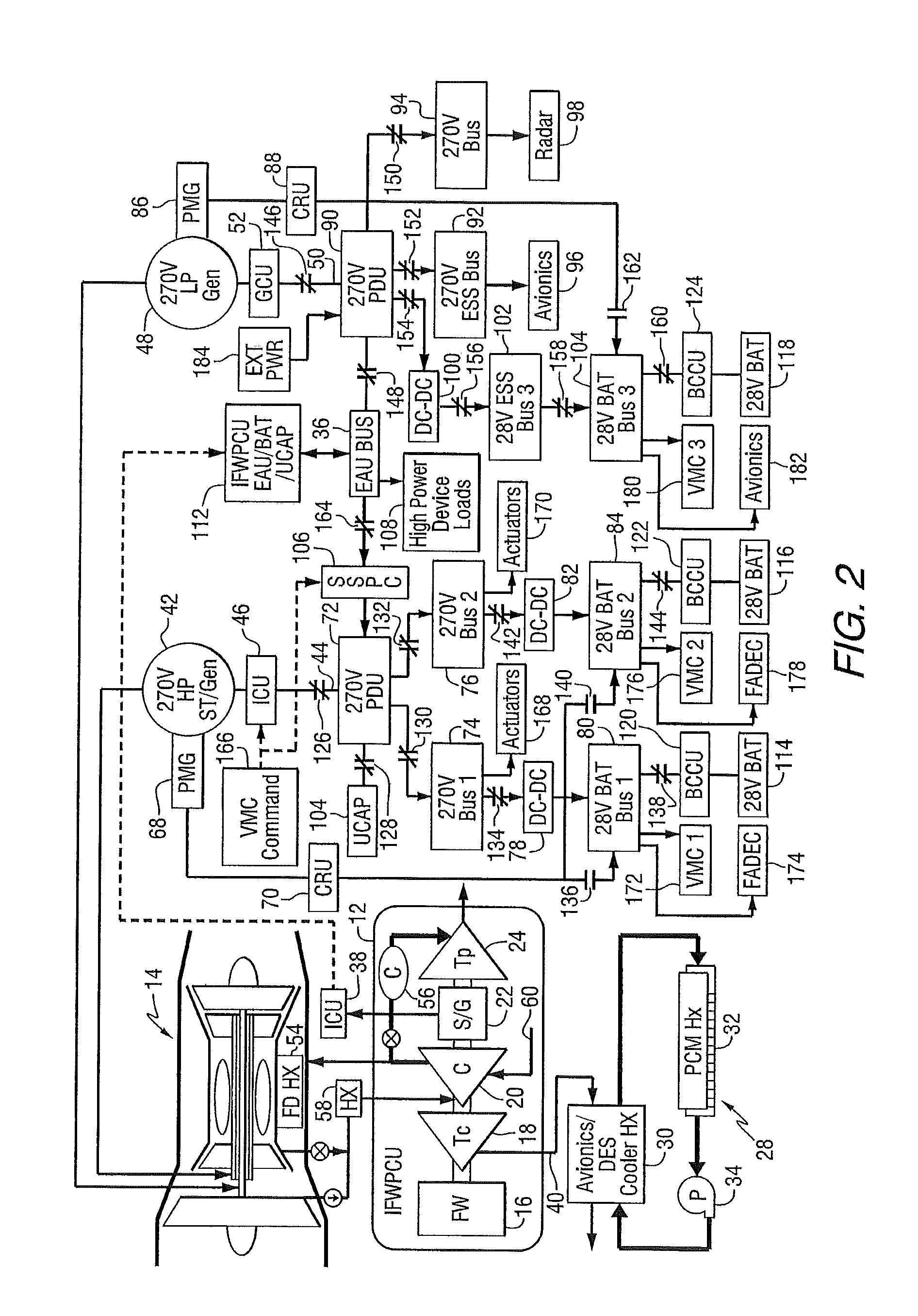
[0011]In one aspect, the invention provides an integrated flywheel power and cooling system (IFWPCS) for an aircraft. In another aspect, the invention provides a power system distribution architecture that operates in combination with the integrated flywheel power and cooling system.

[0012]Aircraft power and cooling systems can be driven by an aircraft engine, for example, using bleed air from the engine. During idle descent flight of an aircraft, engine power extraction and bleed air capability is low and would result in a high penalty if used to drive the power and cooling system. An IFWPCS can use stored energy (e.g., rotation of a flywheel) to assist with power generation and cooling during idle descent flight. In addition, the IFWPCS can provide improved system performance as compared to the state of the art technologies that would be required to enable similar capability.

[0013]FIG. 1 is a schematic block diagram of portions of an aircraft electrical power system 10. The system ...


PUM


Abstract

An apparatus is provided for supplying electrical power and cooling for an aircraft. The apparatus includes a cooling turbine coupled to a shaft, a compressor coupled to the shaft, and including an input for receiving engine bleed air or ambient air, and an output for discharging compressed air, a flywheel coupled to the shaft, a power turbine coupled to the shaft, and a starter generator coupled to the shaft between the compressor and the power turbine.

Description

CROSS-REFERENCE TO A RELATED APPLICATION[0001]This application claims the benefit of U.S. Provisional Patent Application Serial No. 61 / 555,010, filed Nov. 3, 2011, and titled “Apparatus and System Design for Aircraft with High Peak Power Requirement”, which is hereby incorporated by reference.FIELD OF THE INVENTION[0002]This invention relates to electrical power systems, and more particularly to power systems that are capable of satisfying short term peak power demands.BACKGROUND OF THE INVENTION[0003]High performance aircraft require a light weight cooling and power system that has a low impact on the propulsion engine. Such aircraft also need an auxiliary and emergency power source that can provide electrical power both on the ground and in the event of an engine flame out or main generator failure.[0004]Aircraft may also include equipment that requires a high peak power. Such equipment requires power extraction beyond the capability of state-of-the-art (SOA) engine high pressure ...

Claims


Application Information

Patent Timeline
IPC IPC(8): F02C7/00
CPCF02C7/00F02C6/08F02C7/32Y02T50/672Y02T50/53Y02T50/44B64D2013/0696B64D13/06B64D41/00B64D2013/0611B64D2013/0614B64D2013/0674Y02T50/56Y02T50/40Y02T50/50Y02T50/60B64D2013/0644B64D2221/00F02C3/13F02C7/36
Inventor HO, YUHANGKNOWLES, JEFFREY A.
Owner NORTHROP GRUMMAN SYST CORP
Why Eureka
Try Eureka