Rear hub cooling for high pressure compressor

Active Publication Date: 2011-10-13
RTX CORP
View PDF4 Cites 48 Cited by
  • Summary
  • Abstract
  • Description
  • Claims
  • Application Information

AI Technical Summary

Benefits of technology

[0004]In one exemplary embodiment, a gas turbine engine includes a turbine and a high pressure compressor. The high pressure compressor includes a last stage having a last stage compressor blade and a last stage vane. The gas turbine engine includes a first flow path through which bleed air flows to the turbine and a second flow path through which air from the last stage of the high pressure compressor flows. The bleed air in the first flow path exchanges heat with the air in the second flow path in a heat exchanger to cool the air in the second flow path. The cooled air in the second flow path is returned to the high pressure compressor to cool a portion of the high pressure compressor.

Problems solved by technology

Due to material limitations of prior gas turbine engines, the pressure and the rotational speed of the gas turbine engine does not exceed a threshold.

Method used


Image

  • Rear hub cooling for high pressure compressor
  • Rear hub cooling for high pressure compressor
  • Rear hub cooling for high pressure compressor

Examples


Embodiment Construction

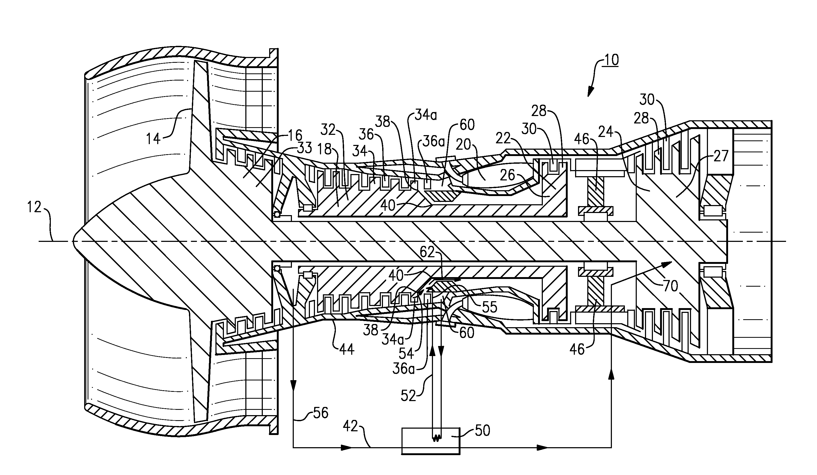
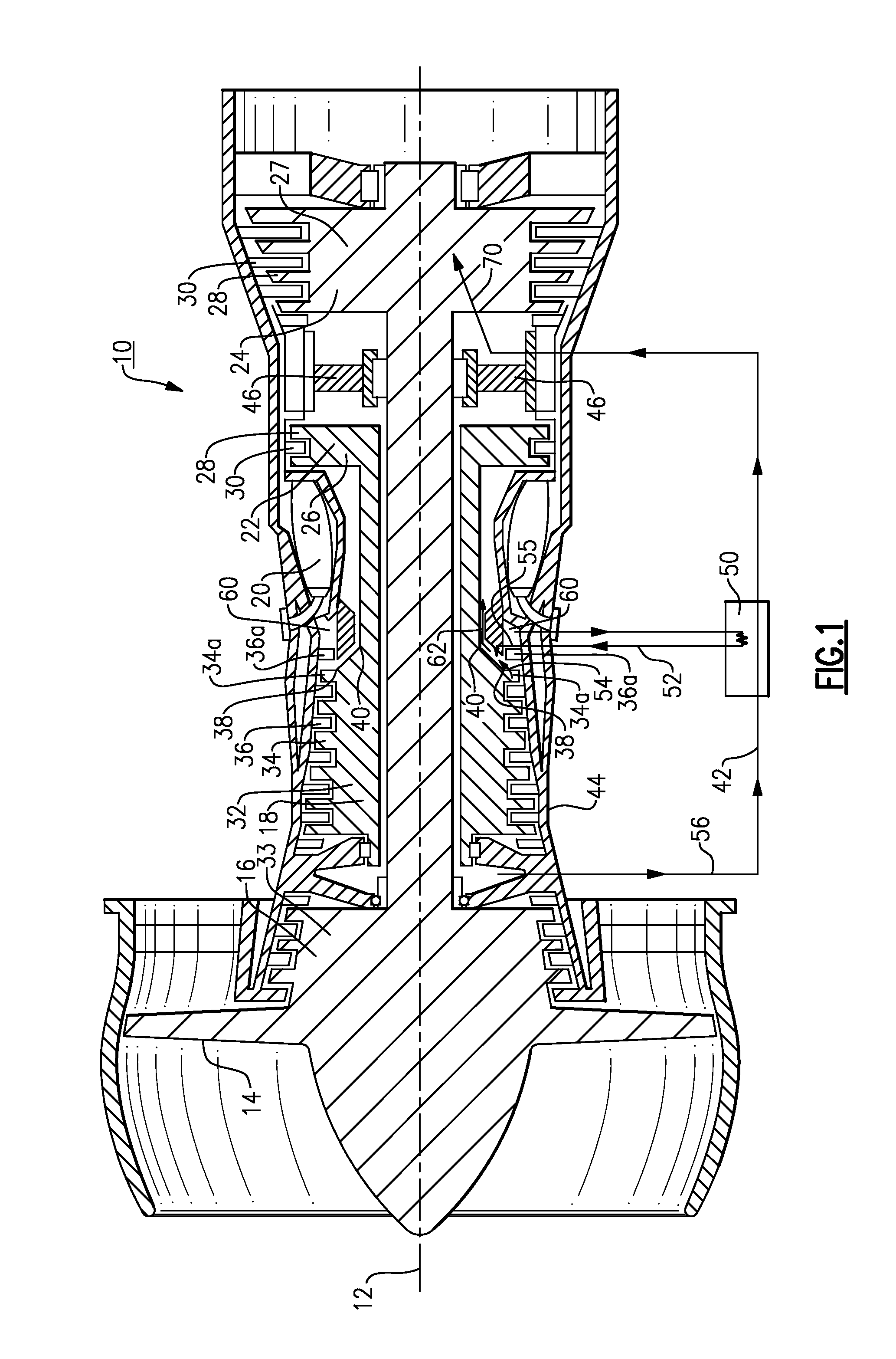
[0014]As shown in FIG. 1, a gas turbine engine 10, such as a turbofan gas turbine engine or a high performance aero-engine gas generator, is circumferentially disposed about an engine centerline (or axial centerline axis 12). The gas turbine engine 10 includes a fan 14, a low pressure compressor 16, a high pressure compressor 18, a combustion section 20, a high pressure turbine 22, and a low pressure turbine 24. This application extends to engines without a fan, and with more or fewer sections. As is well known in the art, air is compressed in the low pressure compressor 16 and the high pressure compressor 18, mixed with fuel and burned in the combustion section 20, and expanded in high pressure turbine 22 and the low pressure turbine 24.

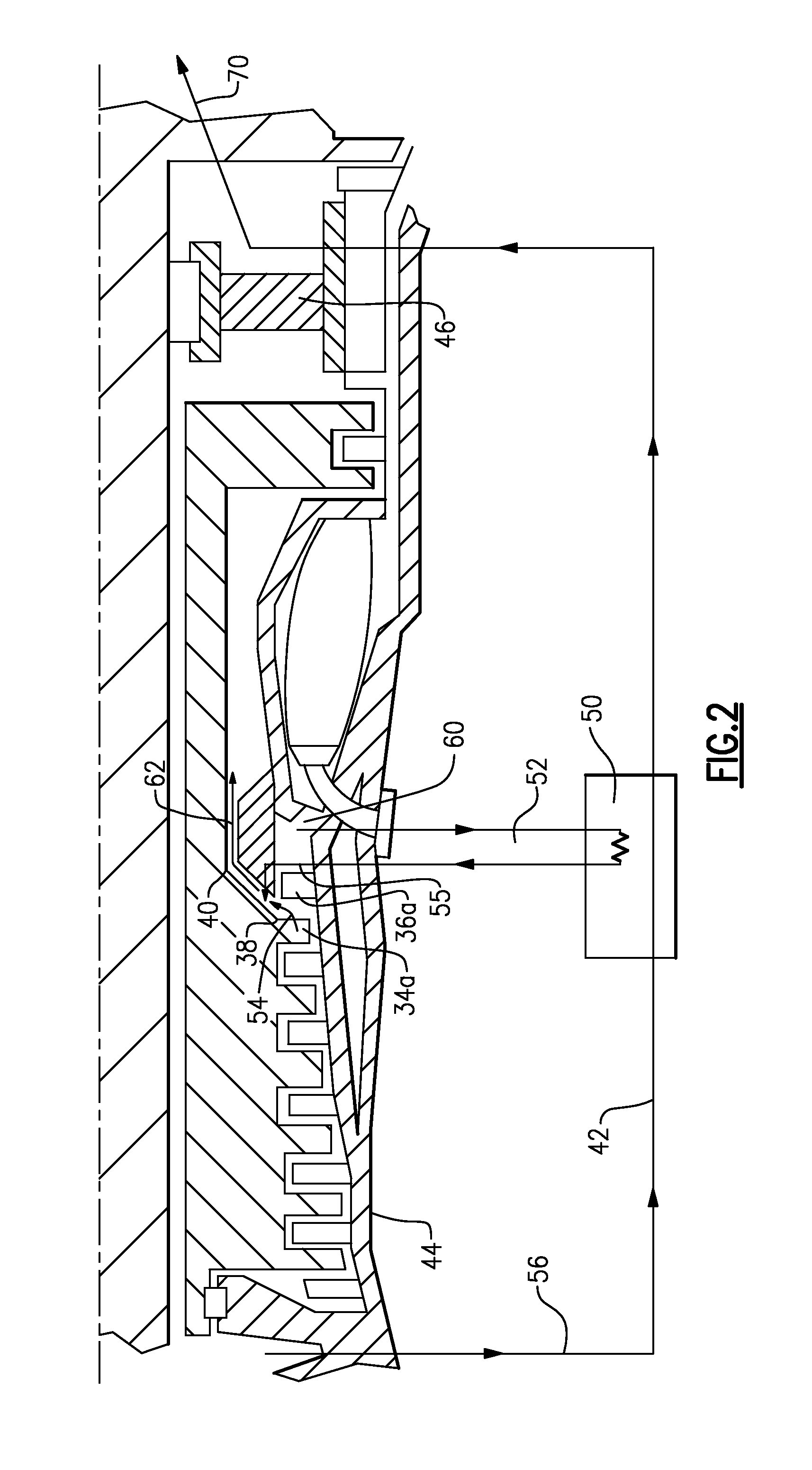
[0015]The high pressure compressor 18 and the low pressure compressor 16 include rotors 32 and 33, respectively, which rotate, driving the high pressure compressor 18, and the low pressure compressor and the fan 14, respectively. The high pressure c...


PUM


Abstract

In one exemplary embodiment, a gas turbine engine includes a turbine and a high pressure compressor. The high pressure compressor includes a last stage having a last stage compressor blade and a last stage vane. The gas turbine engine includes a first flow path through which bleed air flows to the turbine and a second flow path through which air from the last stage of the high pressure compressor flows. The bleed air in the first flow path exchanges heat with a portion of the air in the second flow path in a heat exchanger to cool the air in the second flow path. The cooled air in the second flow path is returned to the high pressure compressor to cool the high pressure compressor.

Description

BACKGROUND OF THE INVENTION[0001]This application relates generally to a system for cooling a rear hub and a rear rim of a high pressure compressor of a gas turbine engine.[0002]In a prior gas turbine engine or a high performance aero-engine gas generator, cool bleed air flows radially inwardly from a casing to cool a mid turbine frame and a low pressure turbine. The air is then exhausted.[0003]Due to material limitations of prior gas turbine engines, the pressure and the rotational speed of the gas turbine engine does not exceed a threshold. Therefore, a last stage of a high pressure compressor of the gas turbine engine does not need to be cooled.SUMMARY OF THE INVENTION[0004]In one exemplary embodiment, a gas turbine engine includes a turbine and a high pressure compressor. The high pressure compressor includes a last stage having a last stage compressor blade and a last stage vane. The gas turbine engine includes a first flow path through which bleed air flows to the turbine and ...

Claims


Application Information

Patent Timeline
Patent Type & Authority Applications(United States)
IPC IPC(8): F02C6/08F02C6/04
CPCF01D5/081F01D9/065F02C6/08F02C7/143F02C7/185F05D2260/205F04D29/5826F04D29/584F05D2260/213F05D2220/3219F04D29/321
Inventor GLAHN, JORN A.MUNSELL, PETER M.JOHNSON, STEVEN B.
Owner RTX CORP
Why Eureka
Try Eureka