Pressure transmitter device

A transmitter and pressure technology, applied in the field of measuring equipment, can solve the problems of inconvenience, complicated operation process, and reduce the efficiency of on-site debugging, and achieve the effect of efficient connection and improvement of work efficiency.

Inactive Publication Date: 2019-11-22
SHANGHAI FL AUTOMATION
View PDF7 Cites 1 Cited by
  • Summary
  • Abstract
  • Description
  • Claims
  • Application Information

AI Technical Summary

Problems solved by technology

As a result, when the pressure transmitter needs to perform parameter modulation, the back cover of the transmitter must be opened, and then the handheld operator is connected to the pos

Method used


Image

  • Pressure transmitter device

Examples


Embodiment 1

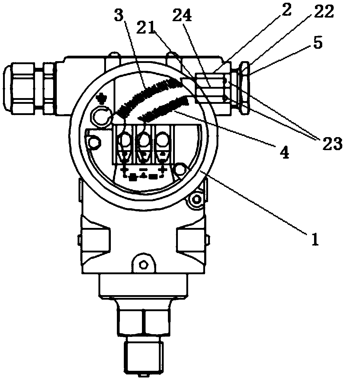
[0020] A pressure transmitter device includes a pressure transmitter 1 and a lead mechanism installed on the pressure transmitter 1 . Wherein, the lead mechanism includes a hollow insulating cylinder 2 , a positive electrode lead 3 and a negative electrode lead 4 .

[0021] The hollow insulating cylinder 2 is cylindrical in shape, fixed to the pressure transmitter 1, and its two sides are respectively open inlet end 21 and outlet end 22;

[0022] A bolt cover 5 is installed on the outlet end 2 of the hollow insulating cylinder 2, and two insulating hanging rods 23 are arranged on the inner wall of the outlet end 2; an insulating partition 24 is also arranged inside the hollow insulating cylinder 2 , The insulating partition 24 divides the interior of the hollow insulating cylinder 2 into two cavities, so that the two insulating hanging rods 23 are respectively located in the two cavities.

[0023] One end of the positive lead wire 3 and the negative lead wire 4 are respective...


PUM


Abstract

The invention discloses a pressure transmitter device, and the device comprises a pressure transmitter and a lead wire mechanism. The lead wire mechanism comprises a hollow insulating cylinder, a positive lead wire and a negative lead wire; the hollow insulating cylinder is fixed with the pressure transmitter, and the two sides of the hollow insulating cylinder are respectively an inlet end and anoutlet end of the opening; a bolt cover is mounted at the outlet end of the hollow insulating column body, and two insulating hanging rods are arranged on the inner wall of one side of the outlet end; one end of the anode lead and one end of the cathode lead are respectively connected with a power supply wiring terminal of the pressure transmitter, and the other ends of the anode lead and the cathode lead extend into the hollow insulating column body from the inlet end and are respectively connected to the two insulating hanging rods. According to the invention, the connection between the pressure transmitter and the manual operator can be efficiently realized, and the working efficiency of the debugging process of the transmitter is improved.

Description

technical field [0001] The invention belongs to the technical field of measuring equipment, and in particular relates to a pressure transmitter device. Background technique [0002] A pressure transmitter is a device that converts pressure into a pneumatic signal or an electric signal for control and remote transmission. It can convert physical pressure parameters such as gas and liquid felt by the load cell sensor into standard electrical signals, which can be supplied to secondary instruments such as indicating alarms, recorders, and regulators for measurement, indication, and process adjustment. The existing pressure transmitter is not provided with a lead wire structure for connecting the handheld operator. As a result, when the pressure transmitter needs to perform parameter modulation, the back cover of the transmitter must be opened, and then the handheld operator is connected to the positive and negative terminals of the pressure transmitter. The existing problem i...

Claims


Application Information

Patent Timeline
IPC IPC(8): G01L1/00
CPCG01L1/00
Inventor 吴文壮
Owner SHANGHAI FL AUTOMATION
Why Eureka
Try Eureka