Binocular vision positioning method and system in dynamic environment

A binocular vision positioning and dynamic environment technology, applied in image analysis, image enhancement, instruments, etc., can solve the problems of real-time impact, high computational complexity of image detection technology, etc., and achieve the effect of improving accuracy

Active Publication Date: 2022-04-19
UNIV OF SCI & TECH OF CHINA
View PDF8 Cites 0 Cited by
  • Summary
  • Abstract
  • Description
  • Claims
  • Application Information

AI Technical Summary

Problems solved by technology

[0003] However, this method has the following disadvantages: (1) The image detection technology itself has high computational complexity, while the positioning technology has high requirements for real-time performance. Adding deep learning and other frameworks to the SLAM system will make the real-time performance greatly affected

Method used


Image

  • Binocular vision positioning method and system in dynamic environment
  • Binocular vision positioning method and system in dynamic environment
  • Binocular vision positioning method and system in dynamic environment

Examples


Embodiment Construction

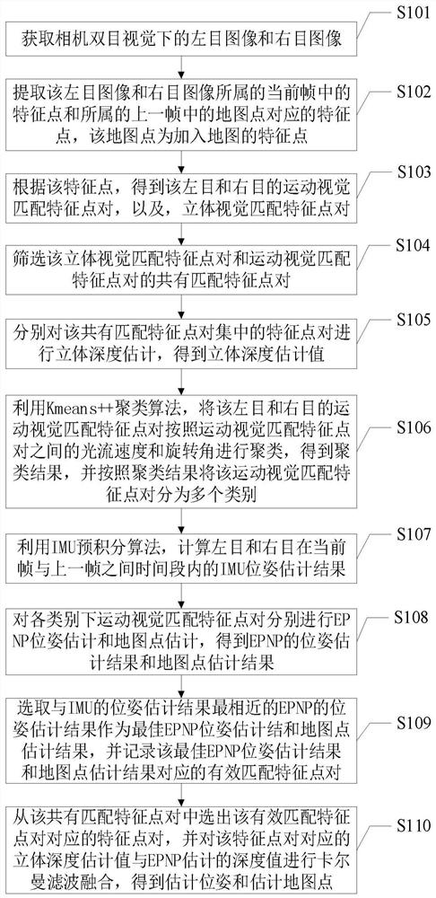
[0069] In order to make the purpose, features and advantages of the present invention more obvious and understandable, the technical solutions in the embodiments of the present invention will be clearly and completely described below in conjunction with the accompanying drawings in the embodiments of the present invention. Obviously, the described The embodiments are only some of the embodiments of the present invention, but not all of them. Based on the embodiments of the present invention, all other embodiments obtained by those skilled in the art without making creative efforts belong to the protection scope of the present invention.

[0070] In this application, the method for screening moving objects is not only applicable to binocular cameras, but also to monocular, multi-purpose, and RGB-D cameras. Therefore, the use of monocular, multi-eye, and RGB-D cameras can also achieve the present invention the goal of. The embodiment of this application takes the visual SLAM al...


PUM


Abstract

A binocular vision positioning method and system in a dynamic environment, which is applied in the field of robot positioning technology, extracts image feature points, and distinguishes feature points on moving objects from feature points on non-moving objects by clustering the feature points. This method can effectively remove the feature points on the moving object, avoid removing the feature points on the static dynamic attribute object, and then retain more available feature points, and use the inter-frame pose transformation matrix obtained by the IMU pre-integration algorithm to filter and The closest IMU data is based on the estimated pose of different feature point sets, so as to effectively eliminate some outliers such as feature points belonging to moving objects; the pose and depth estimation method that combines monocular motion vision and binocular stereo vision, It can effectively improve the estimation accuracy.

Description

technical field [0001] The invention relates to the technical field of robot positioning, in particular to a binocular vision positioning method and system in a dynamic environment. Background technique [0002] Traditional GPS positioning technology is highly dependent on satellite signals, and its accuracy is greatly reduced in environments with many buildings and severe occlusion, especially in indoor environments, which are basically unusable. The inertial navigation technology based on the inertial navigation module (gyroscope, accelerometer) does not rely on external information, and the current position and orientation information of the carrier can be obtained through the integration of its own inertial navigation measurement information, but the inertial navigation positioning error increases with time. The existence of cumulative error, poor long-term accuracy. The vision-based positioning method is to determine the pose of the robot by analyzing the image sequenc...

Claims


Application Information

Patent Timeline
Patent Type & Authority Patents(China)
IPC IPC(8): G06T7/246G06T7/593G06T7/73G06K9/62G06V10/762
CPCG06T7/246G06T7/73G06T7/593G06T2207/10012G06F18/23
Inventor 秦家虎余雷陈宇航
Owner UNIV OF SCI & TECH OF CHINA
Why Eureka
Try Eureka