
L-shaped frame assembling jig

A technology for assembling fixtures and center positioning, which is applied in the field of fixtures, can solve problems such as welding failure, no positioning, motor scrapping, etc., and achieve the effect of good welding, good positioning, and not easy to be relatively dislocated

Pending Publication Date: 2019-11-26
DONGGUAN WORLD PRECISION MACHINERY
View PDF0 Cites 0 Cited by
  • Summary
  • Abstract
  • Description
  • Claims
  • Application Information

AI Technical Summary

Problems solved by technology

During the assembly process, the positioning requirements of the two L frames are high. Once there is a misalignment between the two L frames, welding failure will occur or it will become a defective product after welding. Once the defective product is not found in time, it may affect the performance of the vibration motor. Normal function even causes the motor to be scrapped
Therefore, it is very important to ensure that the relative positions of the two L frames are well positioned before welding, but currently there is no suitable fixture that can properly position the two L frames in the automatic welding equipment

Method used


Image

  • L-shaped frame assembling jig
  • L-shaped frame assembling jig
  • L-shaped frame assembling jig

Examples


Embodiment Construction

[0025] The preferred embodiments of the present invention will be described below in conjunction with the accompanying drawings.

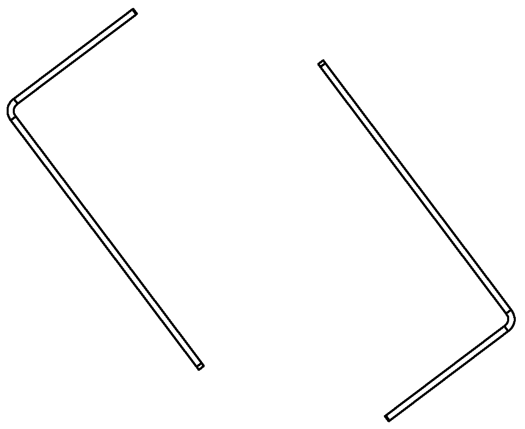
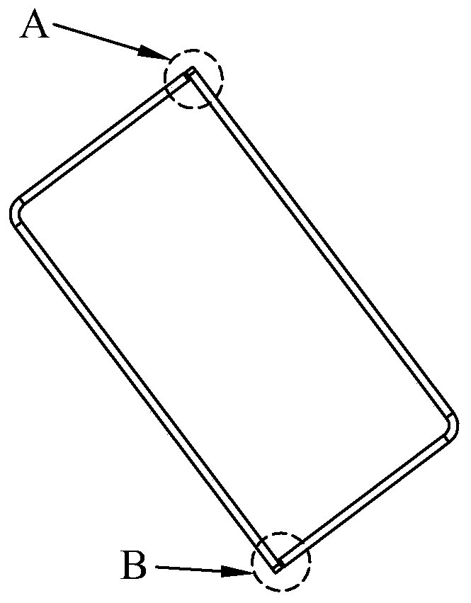
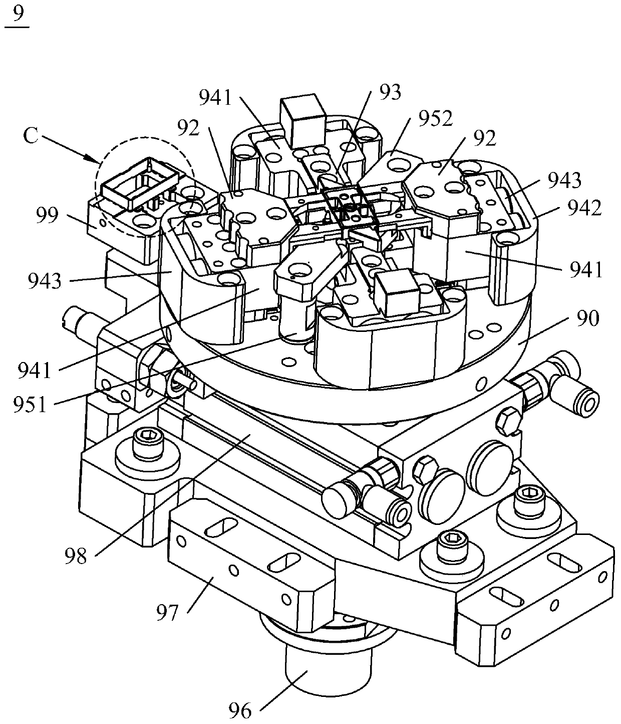
[0026] combine Figure 3 to Figure 5 As shown, the present invention provides a kind of L frame assembly fixture 9, is used for figure 1 The two L boxes shown in the figure 2 The docking status shown in . The L-frame assembly jig 9 includes a bottom plate 90 , a central positioning block 91 and abutting jaws 92 . The center positioning block 91 is fixed in the middle of the base plate 90, and its length and width correspond to the long side and short side size of the L frame respectively, so the two L frames can surround and fit on the outside of the center positioning block 91. Two resisting jaws 92 are slidably arranged on the bottom plate 90 and located on both sides of the central positioning block 91. The resisting jaws 92 can slide close to the central positioning block 91 to press the corresponding L frame against the central positioning...


PUM


Abstract

The invention discloses an L-shaped frame assembling jig. The L-shaped frame assembling jig comprises a bottom plate, a center positioning block fixed to the bottom plate, and two abutting clamping jaws which are slidably arranged on the bottom plate and located on the two sides of the center positioning block; the length and width of the center positioning block correspond to the dimension of thelong side and the dimension of the short side of each L-shaped frame; and the abutting clamping jaws can slidably get close to or away from the center positioning block. According to the L-shaped frame assembling jig, the bottom plate is provided with the center positioning block of which the shape and dimension correspond to those of the two L-shaped frames, and the two abutting clamping jaws, when the two abutting clamping jaws get away from the center positioning block, a feeding mechanical hand of automatic welding equipment can clamp and place the two L-shaped frames on the two sides ofthe center positioning block, then, the abutting clamping jaws slidably get close to the center positioning block and enable the L-shaped frames to abut against the center positioning block, and positioning of the two L-shaped frames is achieved. The two L-shaped frames are positioned with the center positioning block located between the two L-shaped frames as a criterion, moreover, the abutting clamping jaws abut against the L-shaped frames, thus, positioning of the two L-shaped frames is good, relative dislocation is not prone to occurring, and follow-up good welding can be ensured.

Description

technical field [0001] The invention relates to a jig, in particular to an L-frame assembling jig for assembling an L-frame in a vibration motor of a mobile phone. Background technique [0002] figure 1 The two L frames shown are components in the vibration motor of the mobile phone. During the assembly process of the vibration motor, the two L frames need to be assembled as figure 2 Butted into a closed ring as shown in , and welded at two butt positions A, B to fix the two as a whole. During the assembly process, the positioning requirements of the two L frames are high. Once there is a misalignment between the two L frames, welding failure will occur or it will become a defective product after welding. Once the defective product is not found in time, it may affect the performance of the vibration motor. Normal function can even cause the motor to be scrapped. Therefore, it is very important to ensure that the relative positions of the two L frames are well positioned ...

Claims


Application Information

Patent Timeline
IPC IPC(8): B23K37/04
CPCB23K37/0435
Inventor 陈灿华李小会邓春华朴正哲吴健莫齐全
Owner DONGGUAN WORLD PRECISION MACHINERY
Learn More