
Cutting device for foam sandwich plate

A cutting device and sandwich panel technology, applied in the field of foam plastic production, can solve the problems of small application range, inapplicability of panels, unfavorable promotion and use, etc., and achieve the effect of improving service life and reducing high temperature

Inactive Publication Date: 2019-11-26
孙帅
View PDF10 Cites 0 Cited by
  • Summary
  • Abstract
  • Description
  • Claims
  • Application Information

AI Technical Summary

Problems solved by technology

However, when the device cuts the plates, it cannot be applied to plates of different widths, resulting in a small range of use, which is not conducive to popularization and use.

Method used


Image

  • Cutting device for foam sandwich plate
  • Cutting device for foam sandwich plate
  • Cutting device for foam sandwich plate

Examples


Embodiment 1

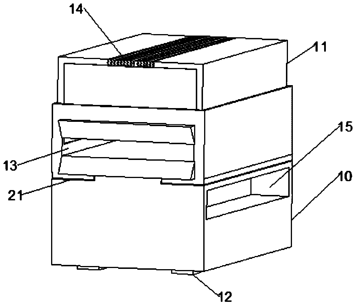
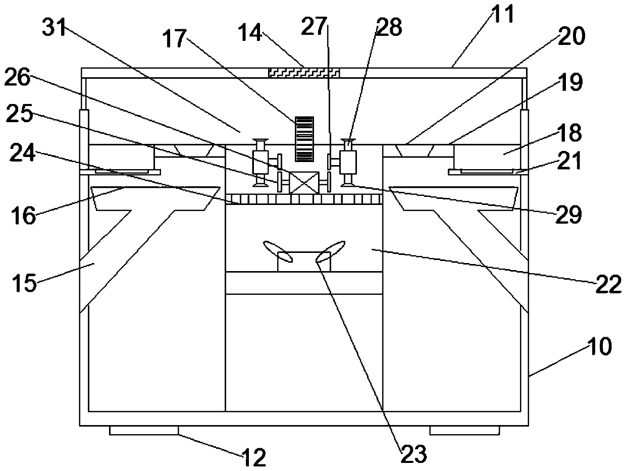
[0020] see Figure 1-2 , a cutting device for a foam sandwich panel, comprising a casing 10, a plate inlet 13, a waste outlet 15 and a cutting knife 17; the four corners of the lower surface of the bottom of the casing 10 are fixedly equipped with anti-slip pads 12, and the anti-slip pads 12 are arranged for improving The stability of the bottom of the casing 10. The front side of the box body 10 is provided with a sheet material inlet 13, and the inside of the sheet material inlet 13 is connected with a cutting channel 31, and the outer end of the sheet material inlet 13 is configured as a trumpet-shaped structure to facilitate the entry of the foam sandwich panel. The box body 10 is arranged as an upper opening shape, and a glass cover 11 is fixedly installed on the top of the box body 10, through which the staff can observe the cutting situation of the foam sandwich panel inside the box body 10. A set of cutting knives 17 is arranged in the middle part of the cutting chann...

Embodiment 2

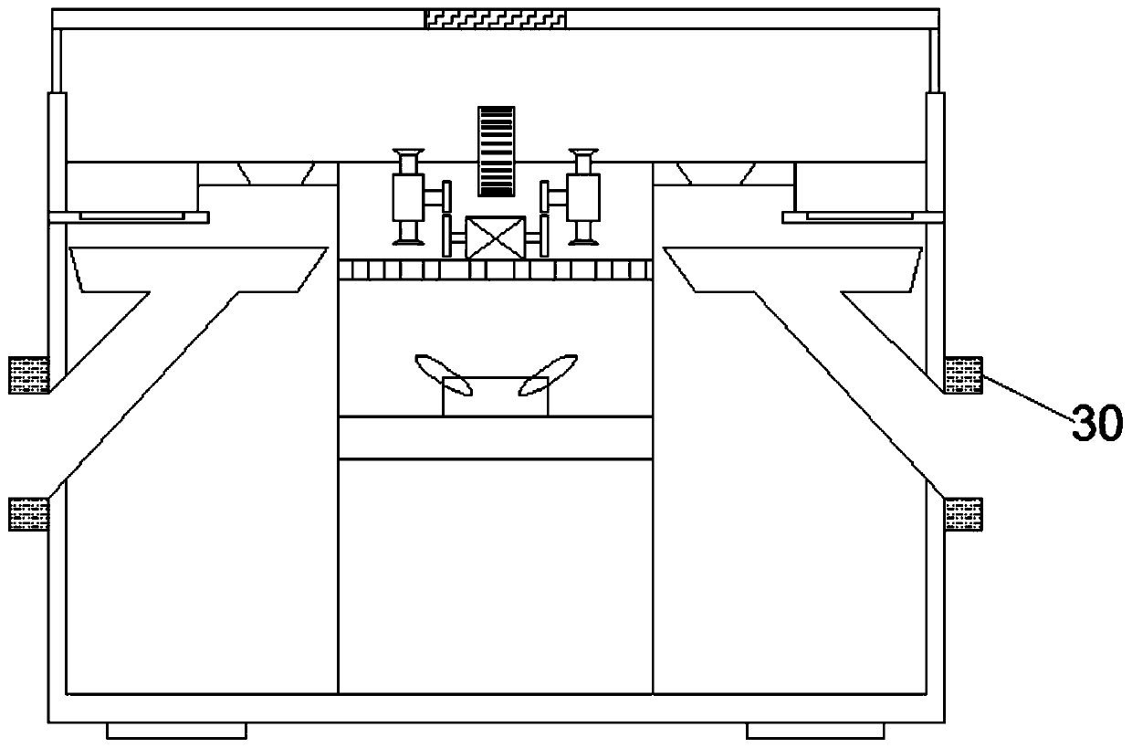
[0024] refer to image 3 , on the basis of Embodiment 1, two sets of exhaust fans 30 are symmetrically installed on the upper and lower sides of the bottom of the waste outlet 15, and by setting the exhaust fans 30 at the bottom of the waste outlet 15, it is convenient to speed up the cutting process of the foam sandwich panel. The output of waste material and dust generated during the process prevents the inside of the waste material outlet 15 from being blocked, which affects the normal use of the cutting.


PUM


Abstract

The invention relates to the technical field of production of foam plastics, and discloses a cutting device for a foam sandwich plate. The cutting device comprises a box body, a plate inlet, a scrap outlet and cutting knives, wherein a group of cutting knives are arranged in the middle of the rear side of a cutting channel; two groups of pulling rods are symmetrically arranged on the left side andthe right side of the bottom parts of the cutting knives; pulling plates are mounted on the upper end and the lower end of the corresponding pulling rod; a driven wheel is mounted inwards in the middle of the corresponding pulling rod through a corresponding connecting rod; the lower side of the corresponding driven wheel is meshed with a corresponding driving wheel; the center of the corresponding driving wheel is rotatably connected with a rotating motor inwards; connecting plates are arranged on the left side and the right side of the cutting channel; a horizontal nesting plate is mountedon the outer side of the corresponding connecting plate in a sleeving manner; the nesting plates are connected with the connecting plates in a sliding manner; the bottom end of the corresponding nesting plate is connected with a movable tank of which one end is fixed to the inner wall of the box body in a sliding manner; multiple groups of discharging holes are formed in the middle of the corresponding connecting plate at equal distances from front to back; and a scrap receiving plate is arranged under the discharging holes. The cutting device disclosed by the invention has the advantages of being wide in application range, quick in automatic operation, high in cutting efficiency and beneficial for popularization and application.

Description

technical field [0001] The invention relates to the technical field of foam plastic production, in particular to a cutting device for foam sandwich panels. Background technique [0002] The foam sandwich panel has beautiful appearance, bright color, good overall effect, and has a wide range of uses. With the wide use of foam sandwich panels, the manufacturing process and equipment requirements need to be continuously improved. The foam sandwich panels are manufactured In the process, it is necessary to go through the cutting process. The quality of the foam sandwich panel cutting is very important for the subsequent use of the foam sandwich panel. [0003] Chinese patent (notification number: CN206357307U, announcement date: 2017.07.28) discloses a foam plastic board cutting device for foam plastic production, including legs, top plate, first connecting rod, slide rail, slider, electric wheel, Driven wheel, pull wire, second connecting rod, block, fixed block, first cylinde...

Claims


Application Information

Patent Timeline
Patent Type & Authority Applications(China)
IPC IPC(8): B26D7/00B26D7/06B26D7/08
CPCB26D7/00B26D7/06B26D7/08
Inventor 孙帅宋忠士
Owner 孙帅
Learn More