
Oil and gas well screen tube structure capable of floating down

A technology of oil and gas wells and screens, which is applied in wellbore/well components, production fluids, earthwork drilling and production, etc. It can solve problems such as inability to achieve sand control effects, failure to run smoothly, and impact on oil and gas production.

Pending Publication Date: 2019-11-26
德州众凯石油科技有限公司
View PDF0 Cites 0 Cited by
  • Summary
  • Abstract
  • Description
  • Claims
  • Application Information

AI Technical Summary

Problems solved by technology

[0002] At present, in the sand control completion process of extended-reach wells or horizontal wells with relatively large vertical wells, if screens are used to complete the well, there are problems of running in the strings that are difficult or even stuck, and cannot be run smoothly to the designed position; If the current floating casing technology recognized in the industry is used, perforation and completion are required after casing running is completed, but this will not achieve the effect of sand control, which will seriously affect the later stage of oil and gas production

Method used


Image

  • Oil and gas well screen tube structure capable of floating down
  • Oil and gas well screen tube structure capable of floating down
  • Oil and gas well screen tube structure capable of floating down

Examples


Embodiment Construction

[0028] In order to clearly illustrate the technical features of this solution, the present invention will be described in detail below through specific implementation modes and in conjunction with the accompanying drawings.

[0029] In the following description, many specific details are set forth in order to fully understand the application, but the application can also be implemented in other ways different from those described here, therefore, the protection scope of the application is not limited by the specific details disclosed below. EXAMPLE LIMITATIONS.

[0030] In addition, in the description of the present application, it should be understood that the terms "center", "upper", "lower", "front", "rear", "left", "right", "vertical", "horizontal" ", "Top", "Bottom", "Inner", "Outer", "Axial", "Radial", "Circumferential" and other indicated orientations or positional relationships are based on the orientations or positional relationships shown in the drawings , is only f...


PUM


Abstract

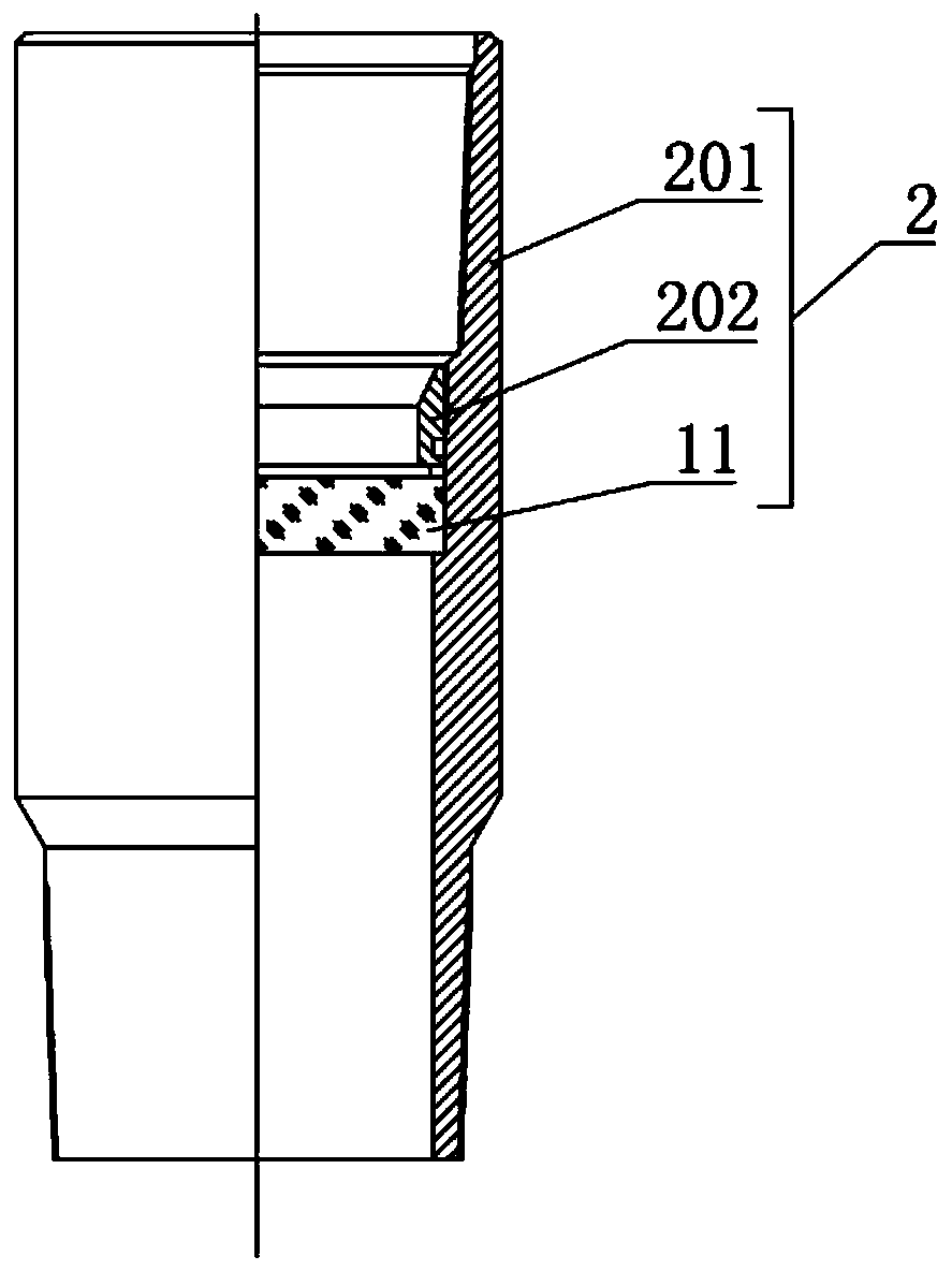
The invention relates to an oil and gas well screen tube structure capable of floating down. The oil and gas well screen tube structure includes a floating screen tube, the floating screen tube includes a first base tube, the bottom end of the first base tube is provided with a guide sealing head, the peripheral outer wall of the top end of the first base tube is connected with the bottom end of asecond base tube, the top end of the second base tube is connected with an upper joint, the tube wall of the second base tube is provided with a flow guide part, the inner side of the second base tube is in communication with the outer side of the second base tube through the flow guide part, and the outer part of the first base tube is provided with a sand control screen tube. According to the oil and gas well screen tube structure capable of floating down, a double-layer composite technology is adopted for the floating screen tube, the floating screen tube is connected with an upper sectioncasing pipe through a pressure bearing nipple, in the horizontal well screen tube well completion construction process, a drilling fluid is blocked on one side of the upper section casing pipe through the pressure bearing nipple so as to keep the floating screen tube in a liquid free state, the double effects of the gravity of the upper section casing pipe of the pressure bearing nipple and the drilling fluid and the buoyancy of the floating screen tube section are used, a tubular column is lowered to the bottom of a well, and the problem of difficulty of lowering of a horizontal well screentube with large displacement is solved.

Description

technical field [0001] The invention relates to a screen pipe structure that can be floated and lowered in oil and gas wells. Background technique [0002] At present, in the sand control completion process of extended-reach wells or horizontal wells with relatively large vertical wells, if the screen is used to complete the well, there will be difficulties in running the string or even sticking problems, and the string cannot be run smoothly to the designed position; If the current floating casing technology recognized in the industry is used, then perforation and completion are required after casing running is completed, but this will not achieve the effect of sand control, which will seriously affect the later stage of oil and gas production. Contents of the invention [0003] The invention provides a screen structure for oil and gas wells that can be floated and lowered. The structure design is reasonable. The screen is connected to the upper section of the casing. Du...

Claims


Application Information

Patent Timeline
IPC IPC(8): E21B43/08
CPCE21B43/086
Inventor 李雷祥孙崇磊李若桐潘荣财刘洪军魏士斌
Owner 德州众凯石油科技有限公司
Learn More