Display panel and display device

A technology of display panel and display area, applied in the direction of computer monitor shell, static indicator, instrument, etc., to achieve the effect of increasing the area, increasing the transmittance, and improving the optical performance

Active Publication Date: 2019-11-26
WUHAN TIANMA MICRO ELECTRONICS CO LTD
View PDF18 Cites 74 Cited by
  • Summary
  • Abstract
  • Description
  • Claims
  • Application Information

AI Technical Summary

Problems solved by technology

[0004] In view of this, an embodiment of the present invention provides a display panel and a display device to solve the problems in the prior art of increasing the transmittance of light penetrating the display panel and improving the performance of optical components under the screen.

Method used


Image

  • Display panel and display device
  • Display panel and display device
  • Display panel and display device

Examples


Embodiment Construction

[0028] In order to better understand the technical solutions of the present invention, the embodiments of the present invention will be described in detail below in conjunction with the accompanying drawings.

[0029] It should be clear that the described embodiments are only some of the embodiments of the present invention, not all of them. Based on the embodiments of the present invention, all other embodiments obtained by persons of ordinary skill in the art without creative efforts fall within the protection scope of the present invention.

[0030] Terms used in the embodiments of the present invention are only for the purpose of describing specific embodiments, and are not intended to limit the present invention. As used in the embodiments of the present invention and the appended claims, the singular forms "a", "said" and "the" are also intended to include the plural forms unless the context clearly indicates otherwise.

[0031] It should be understood that the term "an...


PUM


Abstract

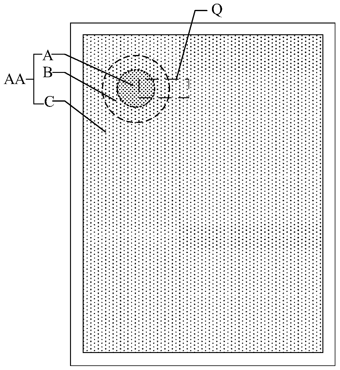
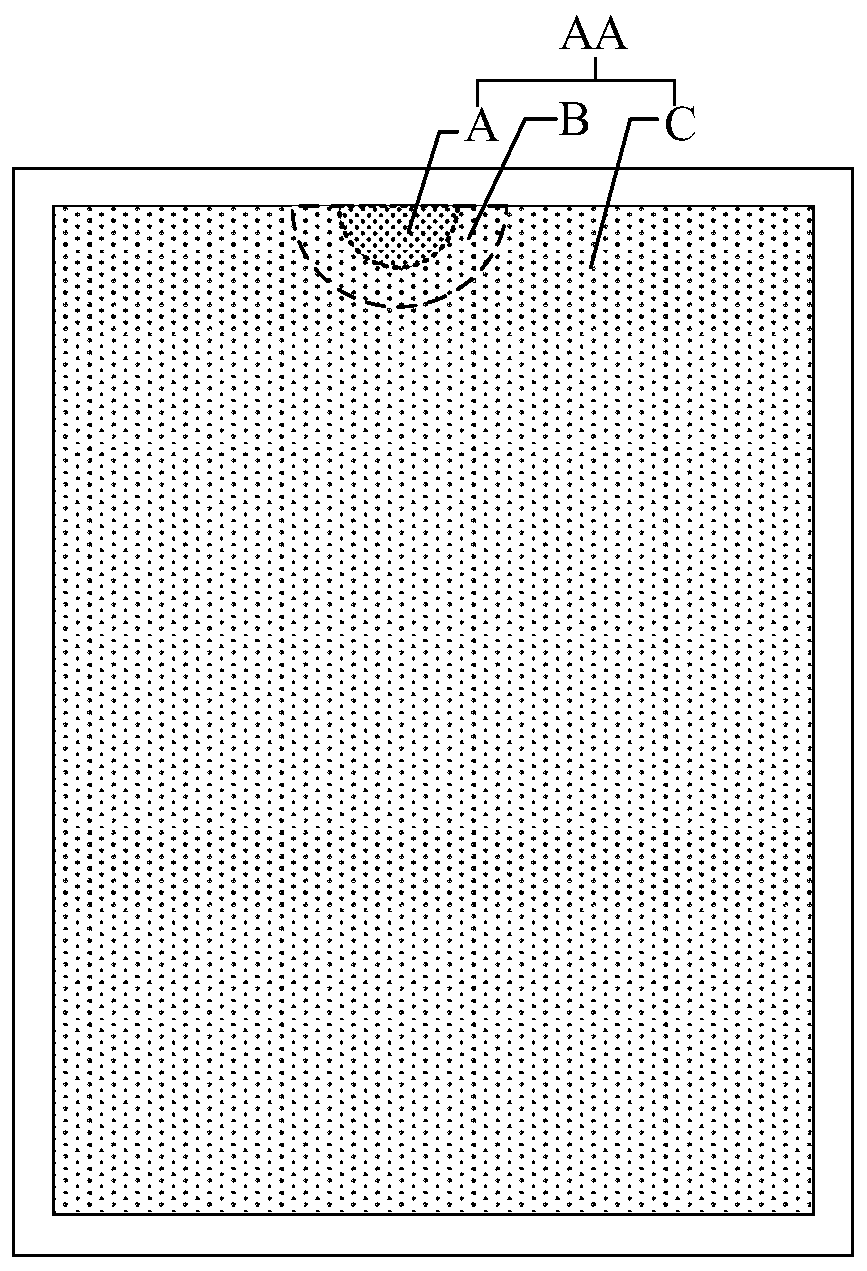
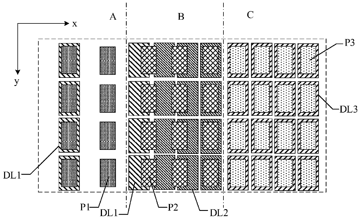
The invention provides a display panel and a display device. The display panel comprises a display area including an optical module setting area, a transition area and a conventional area, wherein thetransition area at least half surrounds the optical module setting area, and the conventional area at least half surrounds the transition area; pixels comprise a first pixel, a transition pixel and aconventional pixel, wherein the first pixel is located in the optical module setting area, the transition pixel is located in the transition area, the conventional pixel is located in the conventional area, the pixel density of the optical module setting area is a first density, the pixel density of the transition area is a second density, the pixel density of the conventional area is a third density, the first density is less than the third density, and the second density is less than the third density; a first pixel circuit is electrically connected to the first pixel, and at least part ofthe first pixel circuit is located in the transition area. The invention can improve the light transmittance of the optical module setting area.

Description

【Technical field】 [0001] The present invention relates to the field of display technology, in particular to a display panel and a display device. 【Background technique】 [0002] With the development of display technology, people not only require a smooth user experience for the electronic products they use, but also have higher and higher requirements for visual experience. High screen-to-body ratio has become the current research direction. For electronic products, the setting of optical modules such as front cameras will inevitably occupy a certain amount of space, thereby affecting the screen-to-body ratio. In order to achieve a true full screen, researchers consider the implementation of optical modules under the screen. [0003] Set the optical module such as the camera under the light-emitting device of the display panel, that is, set the optical module in the display area, and the position of the optical module can be displayed normally. When the optical module needs...

Claims


Application Information

Patent Timeline
Patent Type & Authority Applications(China)
IPC IPC(8): H01L27/32G09G3/3225G09G3/3233
CPCG09G3/3225G09G3/3233H10K59/121H10K59/122H10K59/131G06F1/1626G06F1/1637G06F1/1686H10K59/65G06F1/1605
Inventor 凡艳云
Owner WUHAN TIANMA MICRO ELECTRONICS CO LTD
Why Eureka
Try Eureka