Antenna structure and wearable device with the antenna structure

An antenna structure and wearable device technology, applied in antenna grounding switch structure connections, antennas, antenna components, etc., can solve problems such as inability to receive right-handed circularly polarized electromagnetic waves, inability to flexibly adjust the working frequency band of the antenna, and performance degradation

Active Publication Date: 2021-04-16
出门问问创新科技有限公司
View PDF7 Cites 0 Cited by
  • Summary
  • Abstract
  • Description
  • Claims
  • Application Information

AI Technical Summary

Problems solved by technology

[0004] However, the above antenna structure has the following obvious problems when receiving right-handed circularly polarized electromagnetic waves emitted by GNSS satellites: 1) In theory, using a linearly polarized antenna to receive right-handed circularly polarized electromagnetic waves emitted by GNSS satellites will cause energy loss , the maximum energy loss can reach 3dB, which reduces the receiving performance and affects the positioning speed and positioning accuracy
2) Limited by factors such as the product structure and appearance design of wearable devices, the working frequency band of the right-handed circular polarization of the antenna cannot be flexibly adjusted
3) Restricted by factors such as the product structure and appearance design of wearable devices, the final antenna may be left-handed circularly polarized, which will greatly reduce the performance of receiving GNSS satellite signals, or even fail to receive right-handed circularly polarized electromagnetic waves

Method used


Image

  • Antenna structure and wearable device with the antenna structure
  • Antenna structure and wearable device with the antenna structure
  • Antenna structure and wearable device with the antenna structure

Examples


Embodiment Construction

[0028] The principle and spirit of the present invention will be described below with reference to several exemplary embodiments. It should be understood that these embodiments are given only to enable those skilled in the art to better understand and implement the present invention, rather than to limit the scope of the present invention in any way. Rather, these embodiments are provided so that this disclosure will be thorough and complete, and will fully convey the scope of the invention to those skilled in the art.

[0029] The technical solutions of the present invention will be further elaborated below in conjunction with the accompanying drawings and specific embodiments.

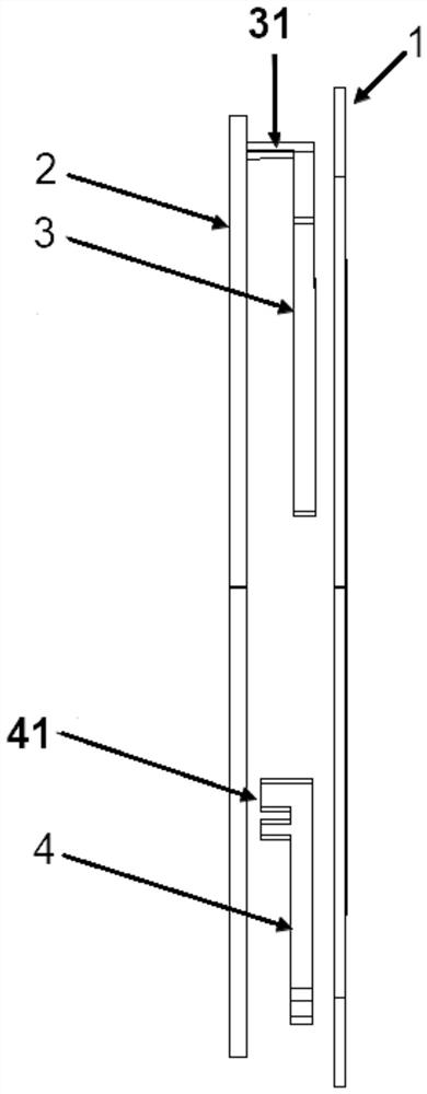
[0030] figure 1 A schematic diagram of an antenna structure according to an embodiment of the present invention is shown. refer to figure 1 , the antenna structure of the embodiment of the present invention includes: a metal piece 1; a circuit board 2 arranged opposite to the metal piece 1, and th...


PUM


Abstract

The invention discloses an antenna structure and a wearable device having the antenna structure. The antenna structure comprises: a metal part; a circuit main board arranged opposite to the metal part, and the gap between the circuit main board and the metal part forms a power feed Space; the coupling antenna arranged in the feeding space, the coupling antenna is coupled and connected with the metal parts, the grounding pin of the coupling antenna is electrically connected to the ground of the circuit board; and the feeding antenna arranged in the feeding space, the feeding antenna is connected to the metal Component coupling connection, the feed source of the feeding antenna is connected to the radio frequency port of the circuit board; wherein, the antenna branch starting from the ground pin of the coupling antenna and the antenna branch starting from the feed source of the feeding antenna are placed on the circumference of the metal part , adjusting the circumferential distance between the feed source of the feeding antenna and the ground pin of the coupling antenna to adjust the frequency band of the right-handed circular polarization of the antenna structure to meet the frequency band of the global navigation satellite positioning system (GNSS).

Description

technical field [0001] The invention relates to the field of electronic communication, in particular to an antenna structure and a wearable device with the antenna structure. Background technique [0002] With the continuous development of electronic communication technology and wearable device technology, wearable devices, especially wearable devices with Global Navigation Satellite System (Global Navigation Satellite System, GNSS) positioning function, are more and more popular. And widely used in various fields. [0003] At present, most wearable devices mainly adopt the following antenna structures: 1) Place the GNSS antenna radiator on a non-metallic shell (such as plastic, ceramic, etc.), and the antenna form is mainly PIFA, IFA, monopole or loop antenna Equilinearly polarized antennas. 2) The metal shell of the wearable device is used as the antenna radiator, and the GNSS linearly polarized antenna is formed by contacting the metal shell with the feeding shrapnel or...

Claims


Application Information

Patent Timeline
Patent Type & Authority Patents(China)
IPC IPC(8): H01Q1/36H01Q1/48H01Q1/50H01Q1/27G01S19/42
CPCG01S19/42H01Q1/273H01Q1/36H01Q1/48H01Q1/50
Inventor 赵志德张博
Owner 出门问问创新科技有限公司
Why Eureka
Try Eureka