
Shell component of permanent magnet motor and permanent magnet motor

A technology of permanent magnet motors and components, which is applied in the direction of electric components, electrical components, casings/covers/supports, etc., which can solve the problems of affecting the operating efficiency and stability of the motor, easy deformation, and high damage rate of the motor. The effect of operating efficiency and running stability, strong impact resistance and strong practicability

Pending Publication Date: 2019-11-26
JIANGSU FULIHUA GENERAL EQUIP
View PDF0 Cites 0 Cited by
  • Summary
  • Abstract
  • Description
  • Claims
  • Application Information

AI Technical Summary

Problems solved by technology

[0003] However, end caps and casings with circular cross-sections have many disadvantages
First of all, the end cover and casing with circular cross-section are easy to form ovality during processing, and because the stress of the end cover and casing with circular cross-section cannot be completely released during use, the end cover and casing are extremely easy to deform, resulting in The bearings in the end cover and the stator assembly in the casing are deformed due to compression, which affects the overall operating efficiency and stability of the motor; secondly, the end cover and casing with a circular cross-section have poor impact resistance and are exposed to strong external forces. It is easy to damage the stator assembly and rotor assembly in the casing under impact; finally, the end cover and casing with a circular cross-section are not easy to limit during transportation, which makes the damage rate of the motor during transportation high

Method used


Image

  • Shell component of permanent magnet motor and permanent magnet motor
  • Shell component of permanent magnet motor and permanent magnet motor
  • Shell component of permanent magnet motor and permanent magnet motor

Examples


Embodiment Construction

[0023] The technical solution of the present invention will be further described below in conjunction with the accompanying drawings.

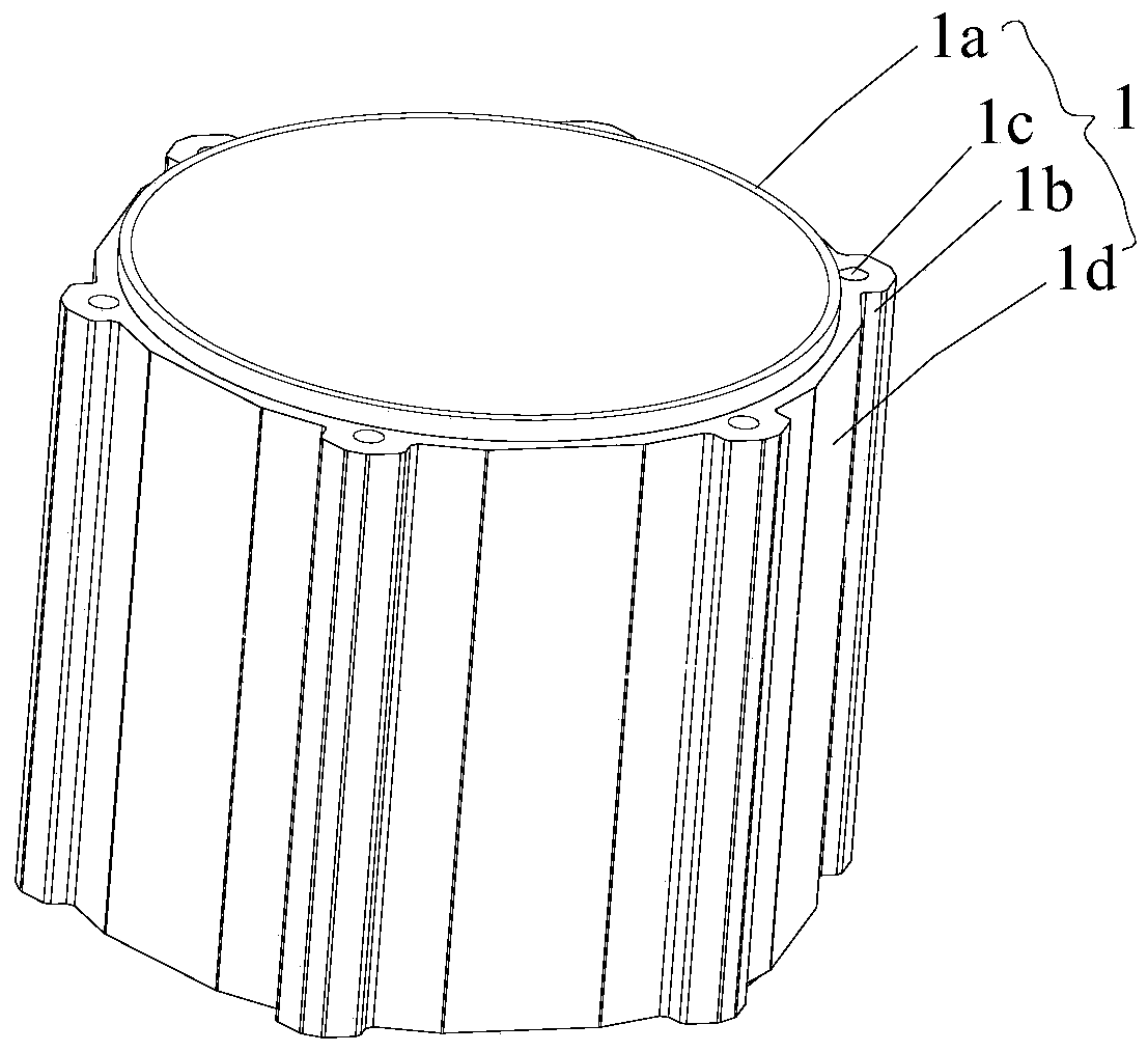
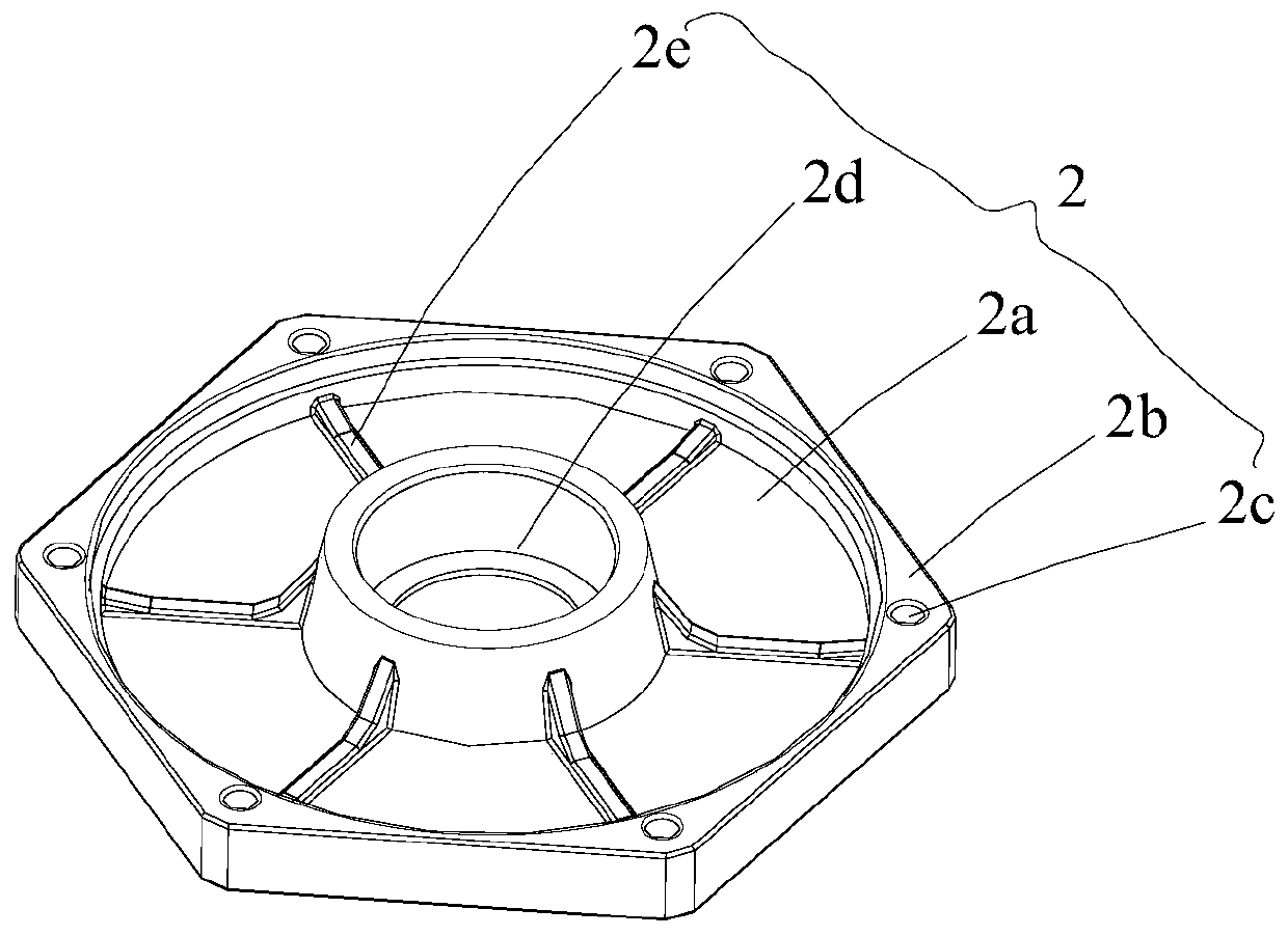
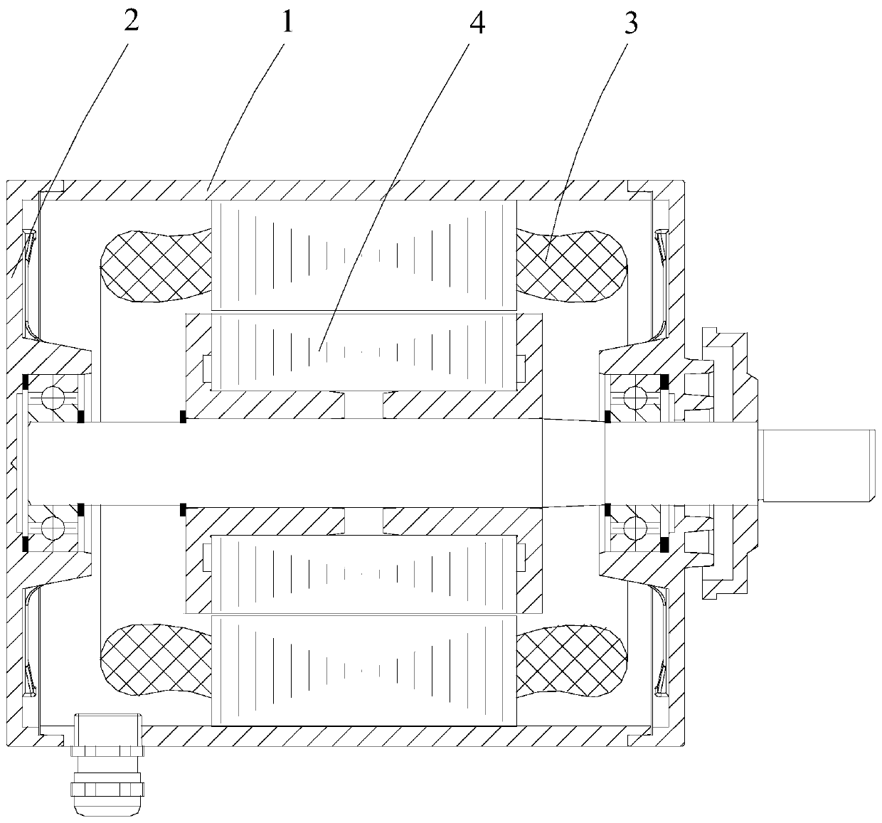
[0024] see Figure 1-3 As shown, a shell assembly of a permanent magnet motor includes a casing 1 and an end cover 2 arranged at the end of the casing 1. The casing 1 includes a casing body 1a with a circular radial cross-section surrounding the casing body. The circumferential ring of 1a is provided on a plurality of first installation parts 1b on the casing body 1a, a first installation hole 1c opened on the first installation part 1b, and a reinforcement part 1d provided between every two first installation parts 1b The end cap 2 includes an end cap body 2a with a circular radial cross section, a second mounting portion 2b with a regular polygonal cross section surrounding the end cap body 2a, and an end portion set at the second mounting portion 2b. And the second installation hole 2c is provided in one-to-one correspondence with the firs...


PUM


Abstract

The invention discloses a shell component of a permanent magnet motor, and the shell component comprises a casing and an end cover, wherein the casing comprises a casing body with a circular radial section, a plurality of first mounting portions circumferentially arranged on the casing body around the casing body, first mounting holes defined on the first mounting portions, and reinforcing portions provided between every two first mounting portions; the end cover comprises an end cover body having a circular radial section, second mounting portions surrounded the outer side of the end cover body and having a regular polygonal cross-section, and second mounting holes defined at the ends of the second mounting portions and provided in one-to-one correspondence with the first mounting holes;the surfaces of one sides of the reinforcing portions close to the casing body are flat and tangent to the outer wall of the casing body, the side walls of the second mounting portions are tangent tothe outer wall of the end cover body, and the reinforcing portions are provided in a one-to-one correspondence with the side walls of the second mounting portions. The above shell component is not easily deformed during processing, and can effectively release internal stresses, thereby greatly ensuring the overall operating efficiency and smoothness of the motor.

Description

technical field [0001] The invention relates to the technical field of permanent magnet motors, in particular to a shell assembly of a permanent magnet motor and the permanent magnet motor. Background technique [0002] Permanent magnet motor is a kind of motor, which has been widely used for its excellent performance. In the existing permanent magnet motors, the radial cross-sections of the end cover and the casing are circular, and the circular cross-sections are convenient to process, so they have been used all the time. [0003] However, end caps and casings with circular cross-sections have many drawbacks. First of all, the end cover and casing with circular cross-section are easy to form ovality during processing, and because the stress of the end cover and casing with circular cross-section cannot be completely released during use, the end cover and casing are extremely easy to deform, resulting in The bearings in the end cover and the stator assembly in the casing ...

Claims


Application Information

Patent Timeline
Patent Type & Authority Applications(China)
IPC IPC(8): H02K5/04H02K5/16
CPCH02K5/04H02K5/161
Inventor 沈坤华张唯陈宁
Owner JIANGSU FULIHUA GENERAL EQUIP
Learn More