POE power supply control device and POE power supply system

A power supply control and power supply terminal technology, which is applied in the field of POE power supply control devices and POE power supply systems, and can solve the problems of inability to perform power management, no relay function, no boost function, etc.

Inactive Publication Date: 2019-11-29
TP-LINK
View PDF9 Cites 8 Cited by
  • Summary
  • Abstract
  • Description
  • Claims
  • Application Information

AI Technical Summary

Problems solved by technology

However, the standard PoE power supply itself has a limited transmission distance. Most of the standard PoE relay devices on the market do not have a boost function, which results in a limited transmission distance.
In addition, because it does not have the relay function to extend the transmission distance of PoE power, it cannot perform power management

Method used


Image

  • POE power supply control device and POE power supply system
  • POE power supply control device and POE power supply system

Examples


Embodiment Construction

[0025] The following will clearly and completely describe the technical solutions in the embodiments of the present invention with reference to the accompanying drawings in the embodiments of the present invention. Obviously, the described embodiments are only some, not all, embodiments of the present invention. Based on the embodiments of the present invention, all other embodiments obtained by persons of ordinary skill in the art without creative efforts fall within the protection scope of the present invention.

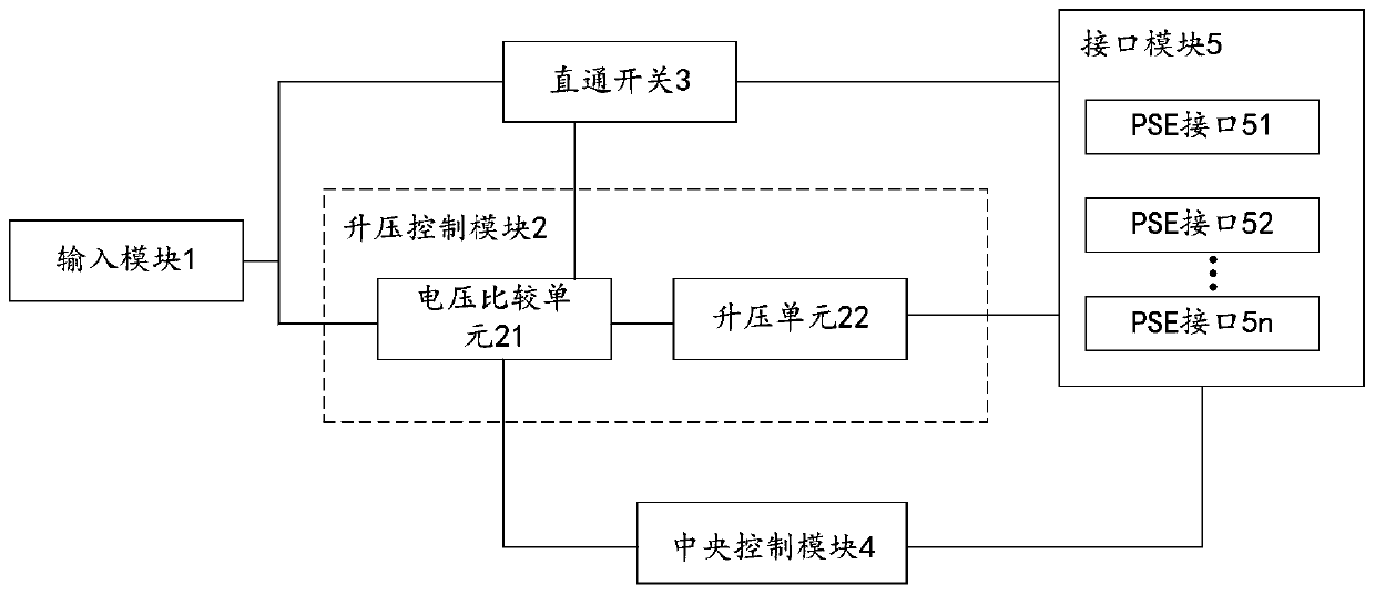
[0026] see figure 1 , figure 1 It is a schematic structural diagram of a POE power supply control device provided by an embodiment of the present invention; the POE power supply control device includes: an input module 1, a boost control module 2, a direct switch 3, a central control module 4, and an interface module 5. The boost control module 2 includes a voltage comparison unit 21 and a boost unit 22, and the interface module 5 includes several interfaces (PSE ...


PUM


Abstract

The invention discloses a POE power supply control device, which comprises an input module, a boost control module, a straight-through switch, a central control module and an interface module, and ischaracterized in that the boost control module comprises a voltage comparison unit and a boost unit, and the interface module comprises a plurality of interfaces used for connecting a POE power receiving end; the voltage comparison unit judges whether the voltage input by the input module is boosted or not; if yes, the boosting unit is enabled, and the boosted voltage is output to the interface module by the boosting unit; if not, the direct connection switch is enabled, and the direct connection switch outputs the voltage to the interface module; and when the central control module responds to the power management instruction sent by the voltage comparison unit, power management is carried out on the interface module according to the connection state of the POE power receiving end and theinterface module and a power application instruction sent by the POE power receiving end. The invention also discloses a POE power supply system. According to the embodiment of the invention, the power supply distance of the standard POE can be effectively extended, and a relay function is realized; and meanwhile, the power is distributed and managed, and a Hub function is realized.

Description

technical field [0001] The present invention relates to the technical field of POE power supply, in particular to a POE power supply control device and a POE power supply system. Background technique [0002] In recent years, there has been a network cable as the medium, through the POE (POE, Power Over Ethernet) power supply system for some IP-based terminal IPAP, network camera, network phone, PDA and other equipment to transmit data signals At the same time, it can also provide DC power supply technology for such devices. The use of POE power delivery systems eliminates the need to install wall power connections for end devices, thus greatly reducing the applied costs associated with supporting end devices. [0003] At present, the latest 802.3bt PoE protocol supports Type3 / 4 power level and can transmit a maximum power of 90W. However, the standard PoE power supply itself has a limited transmission distance, and most of the standard PoE relay devices on the market do n...

Claims


Application Information

Patent Timeline
Patent Type & Authority Applications(China)
IPC IPC(8): H04L12/10
CPCH04L12/10
Inventor 荣挺
Owner TP-LINK
Why Eureka
Try Eureka