
A Traction Power Supply System for Electrified Railway

A traction power supply system, electrified railway technology, applied in power lines, transportation and packaging, vehicle components, etc., can solve the problem of safe operation of trains that affect power supply reliability, large operating overvoltage or overcurrent, traction network and on-board equipment burnout and other problems, to achieve the effect of facilitating daily management, reducing cable consumption, and saving power investment.

Active Publication Date: 2017-08-08
SOUTHWEST JIAOTONG UNIV
View PDF5 Cites 0 Cited by
  • Summary
  • Abstract
  • Description
  • Claims
  • Application Information

AI Technical Summary

Problems solved by technology

The automatic over-phase separation technology mainly includes ground switch automatic switching over-phase separation, vehicle-mounted automatic over-phase separation and column-mounted switch automatic over-phase equalization, but no matter which kind of automatic over-phase separation will cause power supply breakpoints and affect the continuous development of train traction power , at the same time, there is a transient electrical process caused by the switching of the switch when the train is over-phased, which is likely to generate a large operating overvoltage or overcurrent, which may cause accidents such as burning of the traction network and on-board equipment, affecting the reliability of power supply and the safe operation of the train. In addition, phase separation has mechanical weaknesses. Therefore, phase separation is still the weakest link in the entire traction power supply system, and it is the bottleneck of the reliability of traction power supply for high-speed railways and even the entire electrified railway.

Method used


Image

  • A Traction Power Supply System for Electrified Railway
  • A Traction Power Supply System for Electrified Railway
  • A Traction Power Supply System for Electrified Railway

Examples


Embodiment Construction

[0031] The present invention will be further described below in conjunction with the accompanying drawings and specific embodiments.

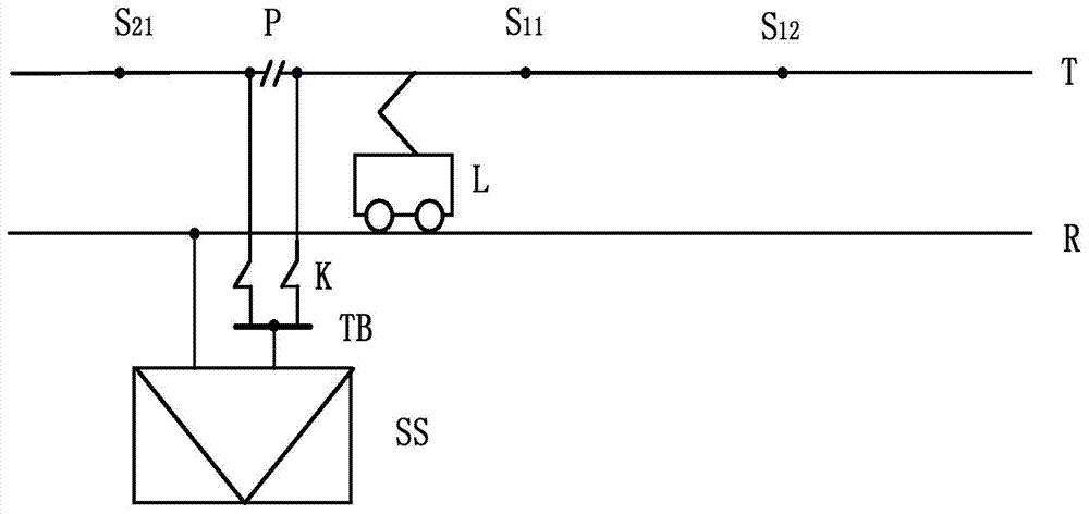
[0032] figure 1Shown is a schematic structural diagram of the direct supply system involved in the present invention. The direct supply system is composed of the traction substation SS and the direct supply traction network. The direct supply traction network is composed of the catenary T and the rail R. The train L receives power between the catenary T and the rail R; The sectionalizer P is set at the exit of the SS, while the catenary generally does not have a sectionalizer S i , but for the convenience of the following description, the subsection S is drawn in the figure i , i=mn, m=1 means the right side of the traction substation SS, m=2 means the left side, n=1,2,...,N, N is the subsection S i number, and the number of segments=N-1, such as figure 1 Medium, S 11 , S 12 , S 21 Wait. In practice, in order to reduce the potential of ...


PUM


Abstract

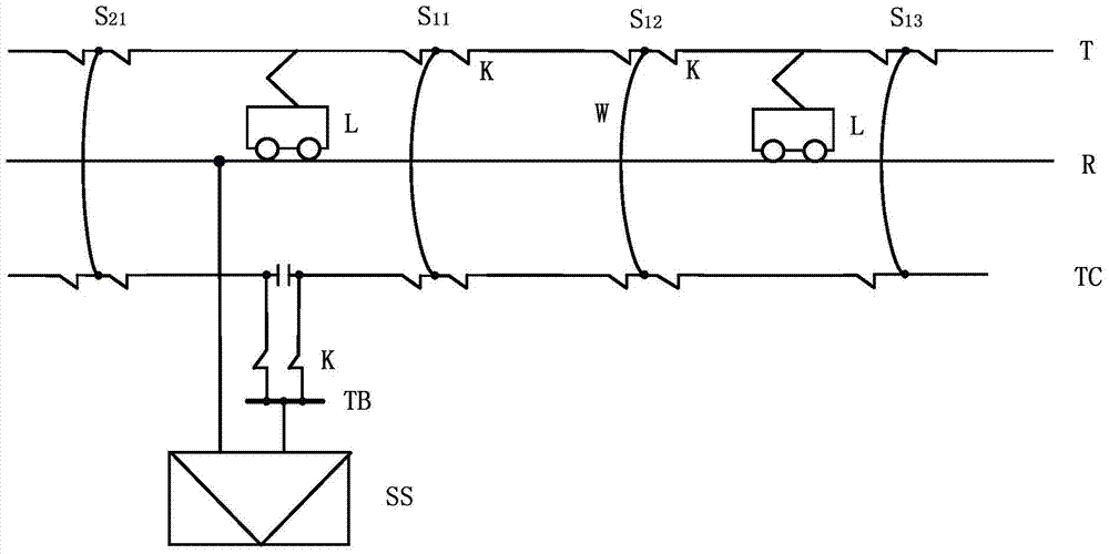
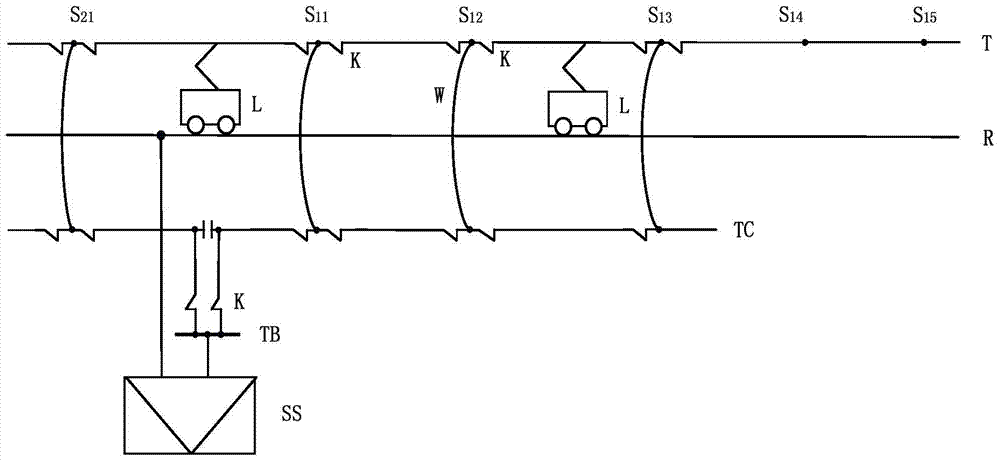
The invention discloses an electrified railway traction power supply system, which belongs to the technical field of electrified railway traction power supply. It can effectively reduce phase separation. Including the traction substation SS, the catenary T and the rail R, wherein the catenary T and the rail R form a direct supply traction network, the traction substation SS supplies power to the traction cable TC through the traction bus TB, and supplies power to the negative feeder through the negative feed bus NB Feeder cable NC power supply; in subsection S i In the above, the traction cable TC and the catenary T are connected in parallel and divided into sections on the first busbar W1 through the switch K, and the negative feeder cable NC and the negative feeder F are connected in parallel and divided into sections on the second busbar W2 through the switch K respectively. The TC end of the traction cable can be connected in series to directly supply the traction network. The ends of the traction cable TC and the negative feeder cable NC can be connected in series with the AT traction network. The power supply capacity and voltage level are mainly determined by the cable. The present invention has strong power supply capacity, long power supply distance and less phase separation, and is suitable for both existing line renovation and new line construction. Mainly used for electrified railway traction power supply.

Description

technical field [0001] The invention relates to the technical field of traction power supply for electrified railways, in particular to the power frequency single-phase traction power supply technology for trunk railways. Background technique [0002] The single-phase traction power supply system has the advantages of simple structure, low construction cost, convenient operation and maintenance, etc., which determines that the power frequency single-phase AC power from the public power grid is generally used to power trains (traction loads) on electrified railways. In order to distribute the single-phase traction load as evenly as possible in the three-phase public grid, the electrified railway adopts the scheme of alternating phase sequence and split-phase power supply. The adjacent power supply areas at the phase-splitting partitions are divided by phase-splitting insulators to form electrical split phases, also known as phase splits. [0003] The phase separation of elec...

Claims


Application Information

Patent Timeline
Patent Type & Authority Patents(China)
IPC IPC(8): B60M3/00
Inventor 李群湛易东王保国解绍锋王祖峰郭锴李强景德炎贺建闽邓琴李亚楠刘再民李志锋刘炜陈民武张丽艳
Owner SOUTHWEST JIAOTONG UNIV
Learn More