Substrate cleaving device

A split and substrate technology, applied in the field of substrate split devices, can solve problems such as excessive bending of the substrate and damage to the surface of the substrate, and achieve the effect of preventing excessive bending

Inactive Publication Date: 2019-12-03
TOP ENG CO LTD
View PDF12 Cites 0 Cited by
  • Summary
  • Abstract
  • Description
  • Claims
  • Application Information

AI Technical Summary

Problems solved by technology

Therefore, in the process of pressurizing the substrate by contacting the tip of the split rod with the substrate, the possibility of damage to the surface of the substrate is high.
In particular, when the tip of the splinter rod contacts a part of the substrate and pressurizes it, the substrate may bend excessively

Method used


Image

  • Substrate cleaving device
  • Substrate cleaving device
  • Substrate cleaving device

Examples


Embodiment Construction

[0028] Hereinafter, the substrate splitting device in the embodiment of the present invention will be described with reference to the drawings.

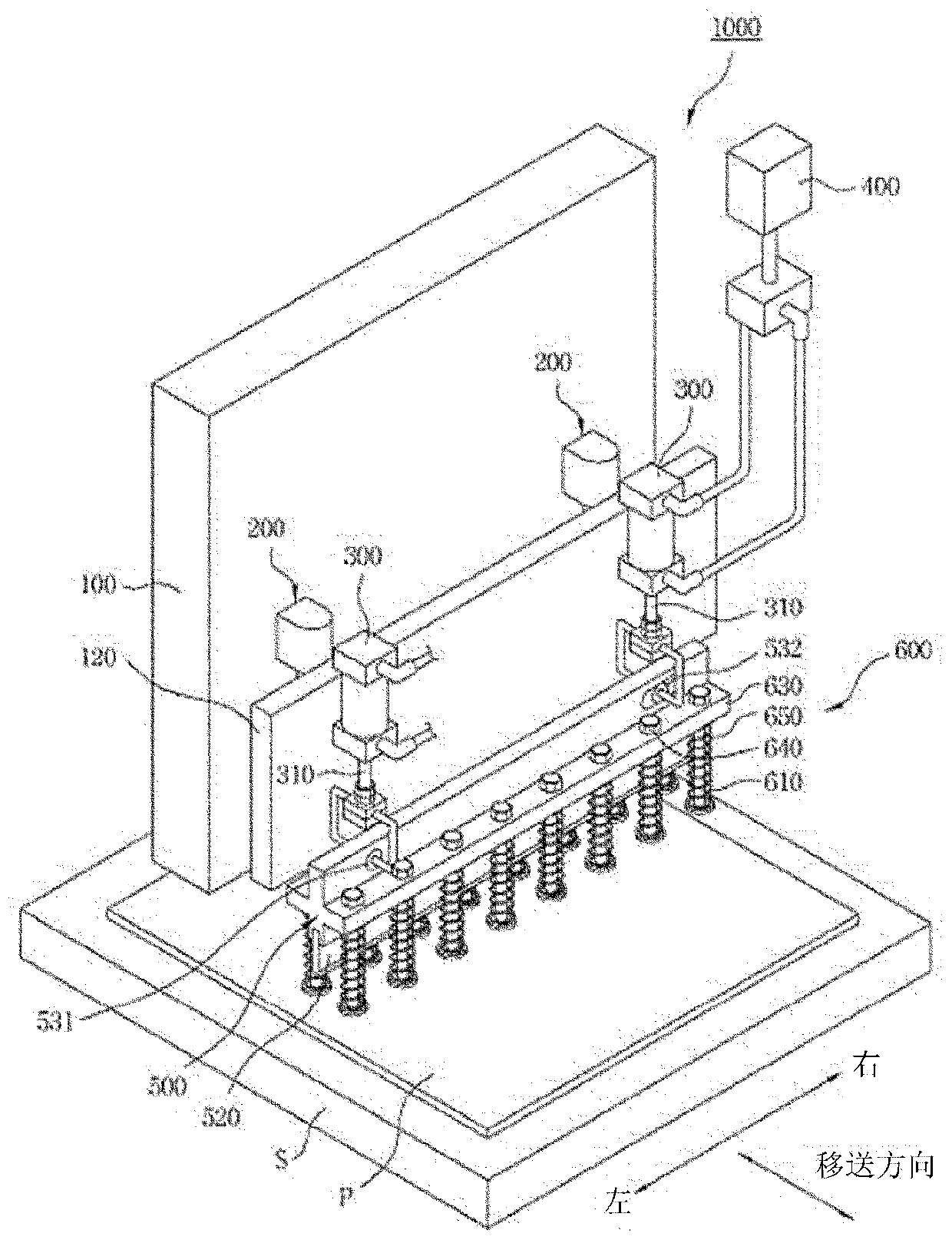
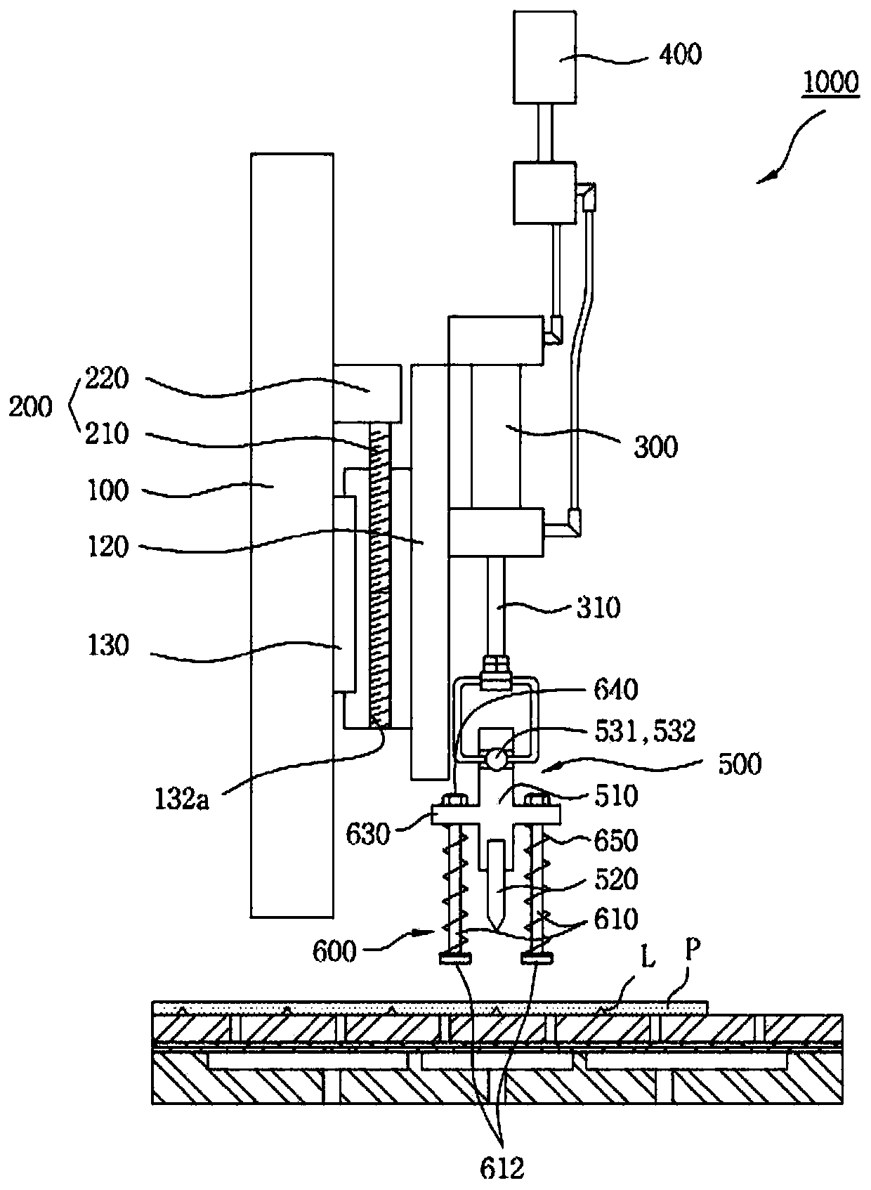
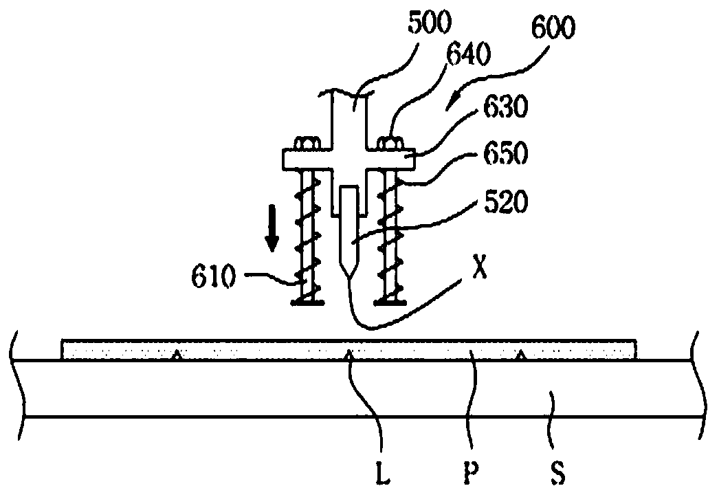
[0029] Such as figure 1 and figure 2 As shown, the substrate splitting device 1000 in the embodiment of the present invention includes: a seat body 100 disposed above the loading table S supporting a substrate P; a transfer unit 200, which is respectively relative to the center of the substrate P in the transfer direction of the substrate P Are arranged on the left and right sides of the seat body 100; the cylinder 300 is arranged on the left and the right with respect to the center of the substrate P in the transfer direction of the substrate P, and the cylinder is moved up and down by the transfer unit 200; pressure adjustment The unit 400 is used to adjust the internal pressure of the cylinder 300; the split head 500, which is connected with the cylinder rod 310 of the cylinder 300, applies pressure to the surface of the substrate P ...


PUM


Abstract

The present invention relates to a substrate cleaving device comprising a cleaving rod that moves toward a substrate to pressurize a surface of the substrate, the cleaving rod comprising: a rod body;a first elastic component arranged at the tail end of the rod body; and a second elastic member provided between the rod body and the first elastic member, the material of the first elastic member having a greater deformation rate with respect to an external force than the material of the second elastic member.

Description

Technical field [0001] The invention relates to a substrate splitting device for breaking a substrate. Background technique [0002] Generally, liquid crystal display panels, organic electroluminescence display panels, inorganic electroluminescence display panels, transmissive projection substrates, reflective projection substrates, etc. used in flat panel displays use unit glass panels (hereinafter referred to as "unit substrates"). The glass panel is obtained by cutting a brittle matrix glass panel such as glass (hereinafter referred to as "substrate") into a predetermined size. [0003] The process of cutting the substrate into unit substrates includes: a scribing process and a slicing process. The scribing process is to press and move a scribing wheel made of materials such as diamond and / Or the substrate is used to form a scribe line on the substrate, and the splitting process is to break the substrate by pressing the substrate along the scribe line to grow the crack of the ...

Claims


Application Information

Patent Timeline
IPC IPC(8): C03B33/033
CPCC03B33/033H01L21/67092H01L21/67259
Inventor 郑下震
Owner TOP ENG CO LTD
Why Eureka
Try Eureka