Building wall spraying device

A spraying device and wall surface technology, which is applied in the direction of architecture and building construction, can solve the problem of not being able to adjust the front and rear positions and distances of the spray pipe at the same time, and achieve the effect of improving the effect of smearing and the smearing area

Active Publication Date: 2019-12-03
王映乐
View PDF8 Cites 6 Cited by
  • Summary
  • Abstract
  • Description
  • Claims
  • Application Information

AI Technical Summary

Problems solved by technology

However, this invention does not divide the spray gun into two parts, and the front and rear positions and distances of the spray pipes on both sides cannot be adjusted at the same time, which has certain limitations.

Method used


Image

  • Building wall spraying device
  • Building wall spraying device
  • Building wall spraying device

Examples


specific Embodiment approach 1

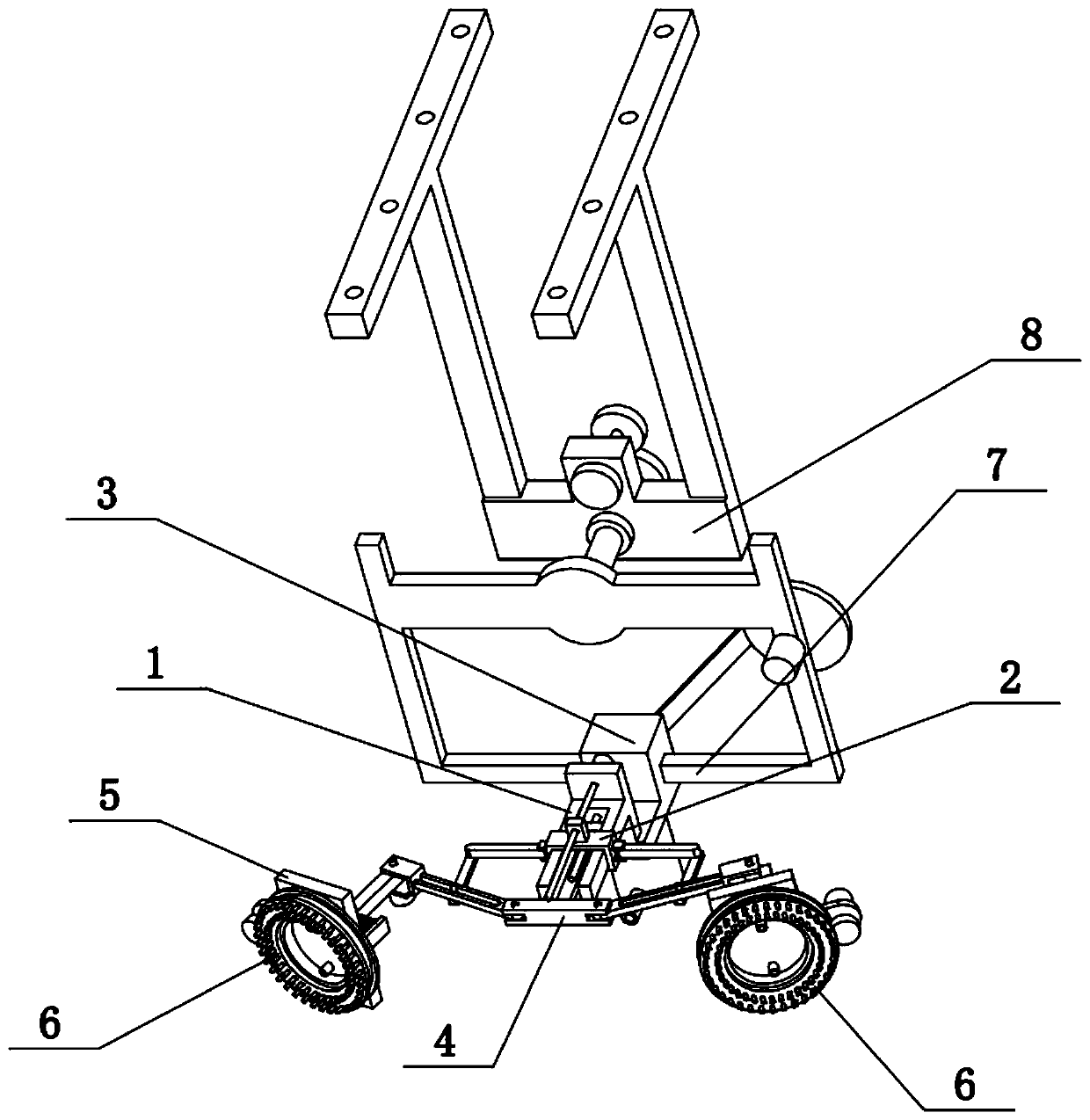
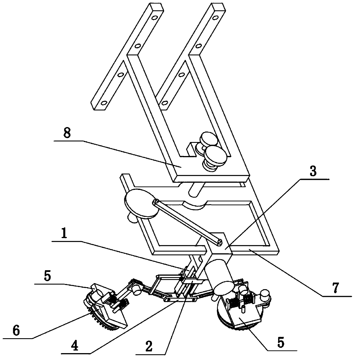
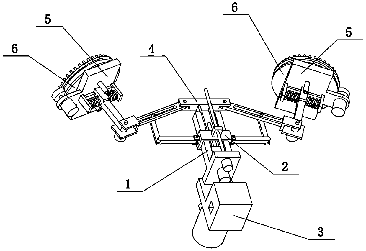
[0035] Combine below Figure 1-11 Describe this embodiment, the present invention relates to the field of building construction, more specifically, a building wall surface spraying device, including a flat seat 1, a flat groove 101, a screw 105, a slip ring 2, an L-shaped folding rod 201, a convex cylinder 202, middle seat 4, sliding hole rod 401, sliding hole 402, hinge seat 403, connecting rod 405, threaded hole block 406, vertical plate 5, material spray pipe 501 and arm lever 505, the present invention can adjust two simultaneously as required The front and rear positions and distances of the risers 5 are convenient for the spray pipes 501 on the two risers 5 to spray the building.

[0036]The flat seat 1 is provided with a flat groove 101, and the threaded hole block 406 is slidably connected to the flat groove 101. The threaded hole block 406 is fixedly connected with two connecting rods 405, and the other ends of the two connecting rods 405 are fixedly connected. There...

specific Embodiment approach 2

[0038] Combine below Figure 1-11 To illustrate this embodiment, the construction wall spraying device further includes a motor III404, which is fixedly connected to the two hinged seats 403, and the output shafts of the two motors III404 are fixedly connected to the two arms 505 respectively. When the output shafts of the two motors III404 rotate, they can respectively drive the two arm levers 505 to rotate on the two hinged seats 403, and then adjust the two vertical plates 5 to a position parallel to the building wall, which is convenient for the vertical plates 5 to rotate. The spray pipe 501 on the top sprays the wall surface.

specific Embodiment approach 3

[0040] Combine below Figure 1-11 Illustrate this embodiment, described building wall spraying device also comprises back seat 102, motor I103, motor II104, lead screw I105 and lead screw II106, the rear end of flat seat 1 is fixedly connected with back seat 102, and the back seat 102 is fixed The motor I103 and the motor II104 are connected, the output shaft of the motor I103 is fixedly connected with a lead screw I105, the output shaft of the motor II104 is fixedly connected with a lead screw II106, the lead screw I105 cooperates with the threaded hole block 406 through threads, and the lead screw 106 Cooperate with slip ring 2 through thread. When the output shaft of motor I103 rotates, it can drive the lead screw I105 to rotate on its own axis. When the lead screw I105 rotates on its own axis, it can control the threaded hole block 406 to slide back and forth on the flat groove 101; It can drive the lead screw II106 to rotate around its own axis, and when the lead screw I...


PUM


Abstract

The invention relates to the field of building construction, in particular to a building wall spraying device. The building wall spraying device provided by the invention has the beneficial effects that the front-rear positions of two vertical plates and the distance between the two vertical plates can be simultaneously adjusted as required, thereby facilitating the spraying onto a building through a plurality of spraying pipes on the two vertical plates; a flat slot is arranged on a flat seat; a threaded-hole block is slidably connected onto the flat slot; two connecting rods are fixedly connected onto the threaded-hole block; a middle seat is fixedly connected between the other ends of the two connecting rods; two sliding-hole rods are correspondingly connected to the left and right endsof the middle seat in a hinging manner; two sliding holes are formed in the two sliding-hole rods; two hinging seats are fixedly connected with the other ends of the two sliding-hole rods; two arm rods are connected onto the two hinging seats in a hinging manner; the two vertical plates are arranged at the other ends of the two arm rods; the multiple spraying pipes are arranged on the two vertical plates; a sliding ring is slidably connected to the outer side of the flat seat; two L-shaped folding rods are fixedly connected with the left and right ends of the sliding ring; and two convex cylinders are fixedly connected with the other ends of the two L-shaped folding rods and slidably connected onto the two sliding holes correspondingly.

Description

technical field [0001] The invention relates to the field of building construction, in particular to a building wall surface spraying device. Background technique [0002] The application number is CN201711176578.2, which discloses a small-scale wall spraying equipment that is easy to adjust. The invention discloses a small-scale wall spraying equipment that is easy to adjust. One side of the inclined plate is fixedly connected with a stirring box, one side of the bottom plate is fixedly connected with a telescopic cylinder, the top of the telescopic cylinder is fixedly connected with a protection box, one side of the top of the protection box is fixedly connected with a support column, and One side of the bottom of the inner wall of the fixed box is fixedly connected with a first motor, the output shaft of the first motor is fixedly connected with a first pulley, and the surface of the first pulley is connected with a second pulley through a belt transmission. This inventio...

Claims


Application Information

Patent Timeline
Patent Type & Authority Applications(China)
IPC IPC(8): E04F21/08
CPCE04F21/08
Inventor 王映乐
Owner 王映乐
Why Eureka
Try Eureka