A Measuring Device for Turbine Blade Rotating Dynamic Airflow Exciting Force

A technology of airflow excitation force and measurement device, which is applied in the directions of safety devices, engine components, machines/engines, etc., can solve the analysis of the forced vibration phenomenon of difficult-to-rotate blades, cannot accurately obtain the position and amplitude of the excitation force, and cannot accurately The size and action position of the airflow exciting force can be obtained in a precise manner, so as to improve the accuracy and reduce the friction effect.

Active Publication Date: 2020-11-10
XI AN JIAOTONG UNIV
View PDF5 Cites 0 Cited by
  • Summary
  • Abstract
  • Description
  • Claims
  • Application Information

AI Technical Summary

Problems solved by technology

[0003] In the vibration experiment of rotating turbine blades, the common method to introduce the exciting force on the blade is to act on the blade through the electromagnet or air flow, and generate a periodic force with exciting dynamic changes during the rotation of the blade. However, these excitation methods The location and amplitude of the exciting force acting on the blade cannot be accurately obtained
Taking the airflow excitation as an example, only data such as the flow rate and direction of the airflow at the outlet of the nozzle can be obtained, but the blade rotation process is a dynamic process, and it is impossible to accurately obtain the airflow excitation force applied to the rotating blade in one cycle The size and action position, which makes the numerical and experimental results in the analysis of blade vibration characteristics unable to carry out effective mutual verification
In the past, the application and measurement methods of blade excitation force were only applicable to the exploration of the vibration of non-rotating blades, and it was difficult to analyze the forced vibration phenomenon of actual rotating blades under the action of airflow.

Method used


Image

  • A Measuring Device for Turbine Blade Rotating Dynamic Airflow Exciting Force
  • A Measuring Device for Turbine Blade Rotating Dynamic Airflow Exciting Force
  • A Measuring Device for Turbine Blade Rotating Dynamic Airflow Exciting Force

Examples


Embodiment Construction

[0035] The present invention will be further described below in conjunction with the accompanying drawings.

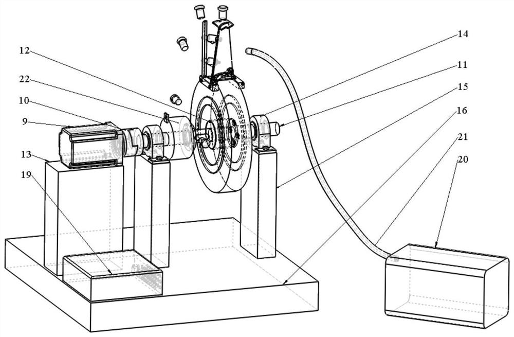
[0036] see figure 1The present invention provides a turbine blade rotation dynamic airflow excitation force measurement device, including a blade disk system, a driving device, an airflow excitation generation device, an excitation force measurement and data acquisition device, a blade tip timing vibration measurement device and a foundation Bench. In the driving device, the servo motor 9 drives the main shaft 11 to rotate at a speed of 60 rpm through the coupling 10 , and the torque is transmitted between the main shaft 11 and the wheel 2 through the expansion sleeve 12 . The main shaft 11 is supported by two bearing blocks 14 , the servo motor 9 and the bearing blocks 14 are installed on the motor mounting platform 13 and the bearing seat mounting platform 15 respectively, and the two mounting platforms are fixed on the base 16 . When it is necessary to introduce t...


PUM


Abstract

The turbine blade rotating dynamic airflow exciting force measuring device comprises a blade disc system, an exciting force measuring device, an airflow exciting generating device and the like. Bladesof the blade disc system are hinged to clamping blocks fixed relative to the position of the wheel disc, the installation direction of a hinged shaft is perpendicular to the first-order bending vibration direction of the blades, and the measurement error of the dynamic airflow exciting force is reduced through polishing and lubricating friction reduction at the hinged position. A dynamic tensionand pressure sensor is introduced along the blade height direction, and is installed along the first-order bending vibration direction of the blade, the side away from the blade is fixed on a rigid measuring rod and the side close to the blade is connected with the blade through a flexible rod, and finally the dynamic process of the amplitude and the action position of the dynamic airflow excitingforce are measured. The excitation force load measured by the method is helpful for perfecting a blade vibration numerical analysis model, a blade non-contact vibration measurement method and the like. By changing the airflow speed, the blade type and the like, different turbine units can be studied, and the universal applicability is achieved.

Description

technical field [0001] The invention belongs to the technical field of experimental devices, and in particular relates to a device for measuring the exciting force of rotating dynamic air flow of turbine blades. Background technique [0002] Turbine blades often work under extremely harsh and complex conditions, and are prone to forced vibrations under the impact of airflow. Practice has shown that the forced vibration of the blade due to the excitation of the airflow is the main cause of the high cycle fatigue failure of the blade. In order to study this forced vibration phenomenon, it is necessary to explore the characteristics of the exciting force, so as to provide a basis for the design of high-life turbine blades. [0003] In the vibration experiment of rotating turbine blades, the common method to introduce the exciting force on the blade is to act on the blade through the electromagnet or air flow, and generate a periodic force with exciting dynamic changes during t...

Claims


Application Information

Patent Timeline
Patent Type & Authority Patents(China)
IPC IPC(8): F01D21/00
CPCF01D21/003
Inventor 张荻蒋明宏赵伟谢永慧
Owner XI AN JIAOTONG UNIV
Why Eureka
Try Eureka