Duty compensation device

A technology of compensation device and duty ratio, which is applied in automatic control of power, pulse processing, electrical components, etc.

Pending Publication Date: 2019-12-03
THINE ELECTRONICS
View PDF3 Cites 0 Cited by
  • Summary
  • Abstract
  • Description
  • Claims
  • Application Information

AI Technical Summary

Problems solved by technology

Sometimes this jitter is

Method used


Image

  • Duty compensation device
  • Duty compensation device
  • Duty compensation device

Examples


Embodiment Construction

[0018] [Description of Embodiments of the Present Invention]

[0019] Firstly, the contents of the embodiments of the present invention will be enumerated and described respectively.

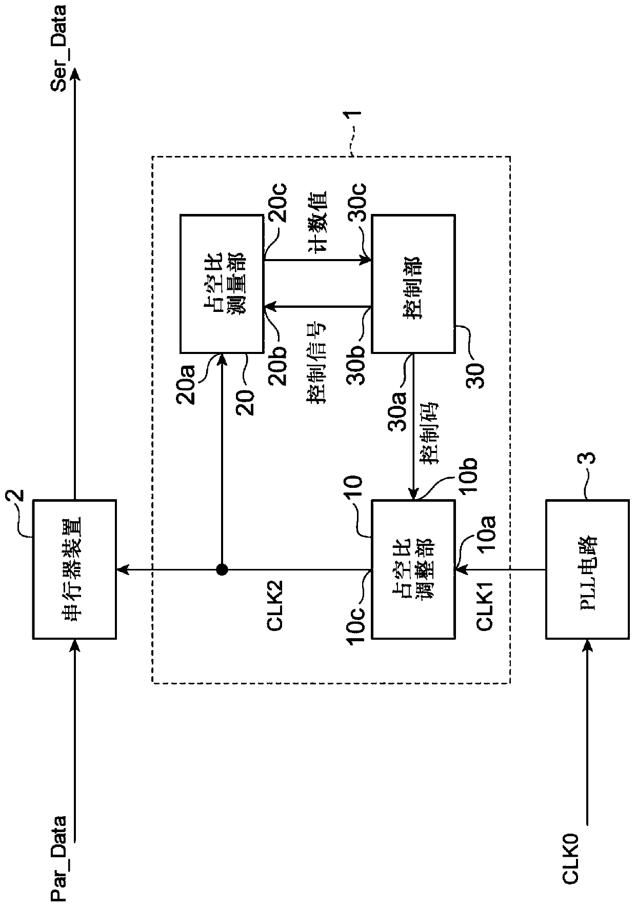
[0020] (1) The duty ratio compensation device of the present embodiment includes, as one aspect thereof, a duty ratio adjustment unit, a duty ratio measurement unit, and a control unit. The duty ratio adjustment unit has a first input terminal for acquiring a pre-adjustment clock, a second input terminal for acquiring a control code, and an output terminal for outputting an adjusted clock. The control code is a control signal for adjusting the duty ratio of the acquired unadjusted clock. The acquired clock before adjustment is adjusted according to the control code. The duty ratio measuring unit has a first input terminal provided for obtaining an adjusted clock, a second input terminal provided for obtaining a control signal, an output terminal provided for outputting a duty ratio for determi...


PUM


Abstract

A duty compensation device of one embodiment has a structure capable of more accurately setting a duty of a clock within an appropriate range. The duty compensation device comprises a duty adjusting unit, a duty measuring unit, a controlling unit. The duty measuring unit generates a sampling clock of a frequency fn that is asynchronous to the clock over an n-th period Tn (n=1 to N and N is an integer of 3 or more), and obtains measurement information for specifying the duty of the clock by using the sampling clock. The controlling unit determines a control code to be given to the duty adjusting unit based on control code candidates obtained for each of the N periods T1 to TN and the control code candidates in which the duty specified by measurement information obtained by the duty measuring unit is within a predetermined range.

Description

technical field [0001] The invention relates to a duty ratio compensation device for compensating the duty ratio of a clock. Background technique [0002] Digital circuits are generally designed to operate in synchronization with a clock. That is, the digital circuit transitions to a new logic state at the timing of both rising and falling of the clock, or any one of them. Alternatively, the digital circuit transitions to a new logic state at the timing of rising or falling of each phase clock constituting the multiphase clock. [0003] In digital circuits, it is important that the duty cycle of the clock is in the proper range. Using the high time t H ratio to period T (t H / T) indicates the duty cycle of a single-phase clock. The duty ratio of the two-phase clock is represented by the ratio of the high-level time of one of the two complementary clocks constituting the two-phase clock to the period. [0004] If the duty ratio of the clock is out of an appropriate rang...

Claims


Application Information

Patent Timeline
IPC IPC(8): H03K5/05H03K5/06
CPCH03K5/05H03K5/06H03K5/135H03K5/1565H03L7/091H03L7/0995H03L7/0805
Inventor 三浦贤藤田悠介
Owner THINE ELECTRONICS
Why Eureka
Try Eureka