Jitter frequency adjusting circuit, method and chip

A technology for regulating circuits and circuits, applied in electrical components, electronic switches, pulse technology, etc., can solve problems such as excessive noise, achieve accurate duty ratio, improve precision, and reduce error

Pending Publication Date: 2021-09-24
SHENZHEN FM ELECTRONICS GRP CO LTD
View PDF0 Cites 1 Cited by
  • Summary
  • Abstract
  • Description
  • Claims
  • Application Information

AI Technical Summary

Problems solved by technology

[0006] Aiming at the defects in the prior art, the present invention provides a frequency shaking adjustment circuit, method and chip, which can improve the accuracy of line network compensation, avoid the problem of excessive noise caused by too concentrated frequency of the circuit, and reduce the impact on the circuit. Electronic components in the device and external electromagnetic interference

Method used


Image

  • Jitter frequency adjusting circuit, method and chip
  • Jitter frequency adjusting circuit, method and chip
  • Jitter frequency adjusting circuit, method and chip

Examples


Embodiment 1

[0037] A frequency shaking adjustment circuit 1, see image 3 , including a sampling module 10 , an oscillation module 20 , a control module 30 and a driving module 40 . Wherein, the sampling module 10 is connected with an external load circuit 50 provided with a switch tube 51 , and the sampling module 10 is configured to acquire a power signal of the external load circuit 50 . The oscillation module 20 is configured to output an oscillation signal. The control module 30 is connected to the sampling module 10 and the oscillation module 20 respectively. The control module 30 is configured to control the jitter interval of the frequency of the oscillation signal according to the load level represented by the power signal, and generate a driving signal based on the frequency of the oscillation signal. The driving module 40 is connected to the switching tube 51 and the control module 30 respectively, and the driving module 40 is configured to control the on-off state of the swit...

Embodiment 2

[0096] A frequency shaking adjustment method, see Figure 11 , including the following steps:

[0097] S1: Obtain the power signal of the external load circuit;

[0098] S2: Control the jitter interval of the frequency of the oscillating signal according to the degree of load represented by the power signal, and generate a driving signal based on the frequency of the oscillating signal;

[0099] S3: Control the on-off state of the switch tube according to the driving signal.

[0100] Further, in some embodiments, controlling the oscillation signal according to the load degree represented by the power signal specifically includes:

[0101] Compare the power signal with the reference signal to generate a comparison result;

[0102] Generate frequency modulation current according to the comparison result;

[0103] Receive FM current and output oscillating signal.

[0104] Further, in some embodiments, the method also includes:

[0105] Obtain the duty cycle of the drive sig...

Embodiment 3

[0109] A frequency shaking adjustment chip includes the frequency shaking adjustment circuit mentioned above.

[0110] The chips provided in the embodiments of the present invention are for brief description, and for those not mentioned in the embodiments, reference may be made to the corresponding content in the foregoing embodiments.


PUM


Abstract

The invention provides a jitter frequency adjusting circuit, method and a chip, and the circuit comprises a sampling module which is connected with an external load circuit provided with a switching tube, and the sampling module is configured to obtain a power signal of the external load circuit; an oscillation module which is configured to output an oscillation signal; a control module which is respectively connected with the sampling module and the oscillation module, wherein the control module is configured to control the jitter interval of the frequency of the oscillation signal according to the load degree represented by the power signal and generate a driving signal based on the frequency of the oscillation signal; and a driving module which is respectively connected with the switching tube and the control module, wherein the driving module is configured to control the on-off state of the switching tube according to the driving signal. According to the circuit, when the voltage at the two ends of the load is relatively high or the current flowing through the load is relatively large, the jitter interval of the frequency of the driving signal of the switching tube is controlled to be reduced, and when the network compensation is carried out, the obtained duty ratio of the switching tube is accurate and the error is relatively small, so that the accuracy of the network compensation is improved.

Description

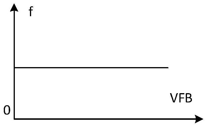
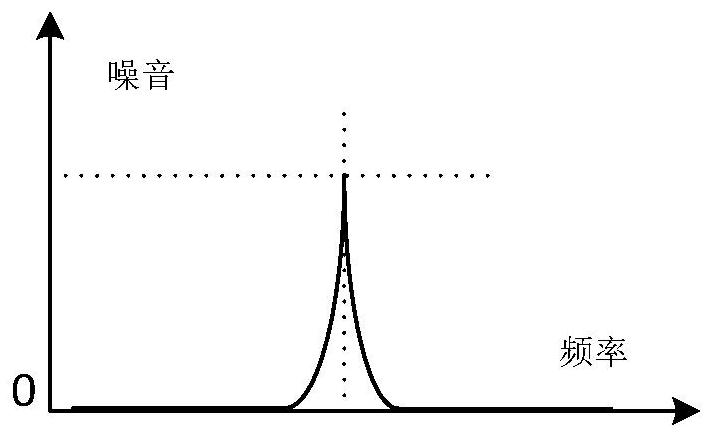
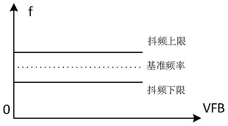
technical field [0001] The invention belongs to the technical field of integrated circuits, and in particular relates to a frequency shaking adjustment circuit, a method and a chip. Background technique [0002] In the current driving circuit for driving the switch, since the frequency of the driving switch is in a fixed state (such as Figure 1a shown), so it will cause the circuit noise generated in the circuit to be too concentrated (such as Figure 1b As shown), the noise of the circuit is too large, which will cause electromagnetic interference to the electronic components in the circuit and affect the performance of the circuit. [0003] In order to improve this problem, the prior art usually configures a frequency shaking function in the circuit, so that the frequency of the driving switch is within a certain range. Such as Figure 2a As shown, when frequency shaking is configured for the circuit, the frequency at which the switch is driven fluctuates within a fixed...

Claims


Application Information

Patent Timeline
Patent Type & Authority Applications(China)
IPC IPC(8): H03K17/16
CPCH03K17/16
Inventor 卢山李科举
Owner SHENZHEN FM ELECTRONICS GRP CO LTD
Why Eureka
Try Eureka