oscillator

A technology of oscillators and inverters, applied in the field of oscillators with a duty cycle of 50%, can solve the problems of large circuit area and high power consumption, and achieve the effects of accurate duty cycle, power consumption optimization, and area saving

Active Publication Date: 2016-12-28
SHANGHAI HUAHONG GRACE SEMICON MFG CORP
View PDF5 Cites 0 Cited by
  • Summary
  • Abstract
  • Description
  • Claims
  • Application Information

AI Technical Summary

Problems solved by technology

[0004] In order to overcome the problem of large circuit area and high power consumption in the above-mentioned prior art, the main purpose of the present invention is to provide an oscillator, which can be realized by using a relatively simple charge and discharge circuit, a comparator, and a D flip-flop. A clock signal with a duty cycle of 50%, not only saves 50% area, optimizes power consumption, but also has a more accurate duty cycle

Method used


Image

  • oscillator
  • oscillator
  • oscillator

Examples


Embodiment Construction

[0022] The implementation of the present invention is described below through specific examples and in conjunction with the accompanying drawings, and those skilled in the art can easily understand other advantages and effects of the present invention from the content disclosed in this specification. The present invention can also be implemented or applied through other different specific examples, and various modifications and changes can be made to the details in this specification based on different viewpoints and applications without departing from the spirit of the present invention.

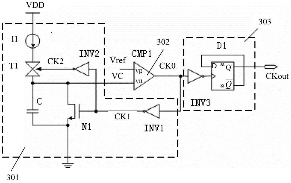
[0023] image 3 It is a schematic circuit diagram of the first preferred embodiment of an oscillator of the present invention. Such as image 3 As shown, an oscillator of the present invention includes: a charging and discharging module 301 , a shaping module 302 and a duty cycle adjusting module 303 .

[0024] Wherein, the charging and discharging module 301 is connected with a power sup...


PUM


Abstract

The invention discloses an oscillator. The oscillator comprises a charge-discharge module, a shaping module and a duty ratio regulation module, wherein the charge-discharge module is connected with supply voltage and produces sawtooth wave, through charging and discharging, to be output to the shaping module; the shaping module is provided with two input terminals which are respectively connected with reference voltage and sawtooth wave output of the charge-discharge module, and produces narrow pulse to be sent to the duty ratio regulation module after comparing the reference voltage with the sawtooth wave output; and the duty ratio regulation module performs frequency division on the narrow pulse, so as to obtain clock signals, with the duty ratio being of 50 percent. The oscillator can realize the clock signals, with the duty ratio being 50 percent, through a simple charge-discharge circuit, a comparator and a D trigger only, not only saves 50 percent of area and optimizes power consumption, but also is more accurate in duty ratio.

Description

technical field [0001] The present invention relates to an oscillator, in particular to an oscillator with a duty cycle of 50%. Background technique [0002] EEPROM (Electrically Erasable Programmable Read-Only Memory, Electrically Erasable Programmable Read-Only Memory) often needs to use an oscillator to generate the clock required by the high-voltage charge pump. Generally, the charge pump is most efficient when the clock duty cycle is 50%. figure 1 For a conventional oscillator circuit schematic, figure 2 A schematic diagram of the simulation results of a traditional oscillator. Such as figure 1 and figure 2 As shown, the oscillator includes transmission gate T1 / T2, current source I1 / I2, comparator CMP1 / CMP2, NAND gate AND1 / AND2 and inverter INV1 / INV2 / INV3 / INV4 / INV5. The basic principle is: At the beginning, VC is 0, the comparator CMP1 outputs low level 0, and the comparator CMP2 outputs high level 1, so the NAND gate AND1 outputs high level 1, and the NAND gate A...

Claims


Application Information

Patent Timeline
Patent Type & Authority Patents(China)
IPC IPC(8): H03K3/02
Inventor 冯楚华杨光军
Owner SHANGHAI HUAHONG GRACE SEMICON MFG CORP
Why Eureka
Try Eureka