
Screw targeting guide system and method

A technology of guiding parts and guiding elements, which can be used in fastening devices, medical science, surgery, etc., and can solve problems such as increasing operation time and increasing pain.

Inactive Publication Date: 2019-12-03
WRIGHT MEDICAL TECH
View PDF6 Cites 0 Cited by
  • Summary
  • Abstract
  • Description
  • Claims
  • Application Information

AI Technical Summary

Problems solved by technology

Repeated insertion and removal of introducer elements results in additional wounds for the patient and increases pain, recovery time, and surgical complexity (including difficulty, increased operative time, etc.)

Method used


Image

  • Screw targeting guide system and method
  • Screw targeting guide system and method
  • Screw targeting guide system and method

Examples


Embodiment Construction

[0032] The description of the exemplary embodiments is intended to be read in conjunction with the accompanying drawings, which are considered a part of the entire written description. In descriptions such as "below", "upper", "horizontal", "vertical", "above", "below", "upward", "downward", "top", "bottom", "near side ", "far side", "superior", "inferior", "middle" and "lateral" and their derivatives (for example, "horizontally", "downwardly", "upwardly", etc.) Relative terms should be construed to refer to an orientation described subsequently or shown in the figure in question. These relative terms are for convenience of description and do not require that the device be constructed or operated in a particular orientation. Terms referring to attached, coupled, etc. (such as "connected") refer to a relationship in which structures are fixed or attached to each other, directly or indirectly through intermediate structures, as well as both movable or rigid attachments or relat...


PUM


Abstract

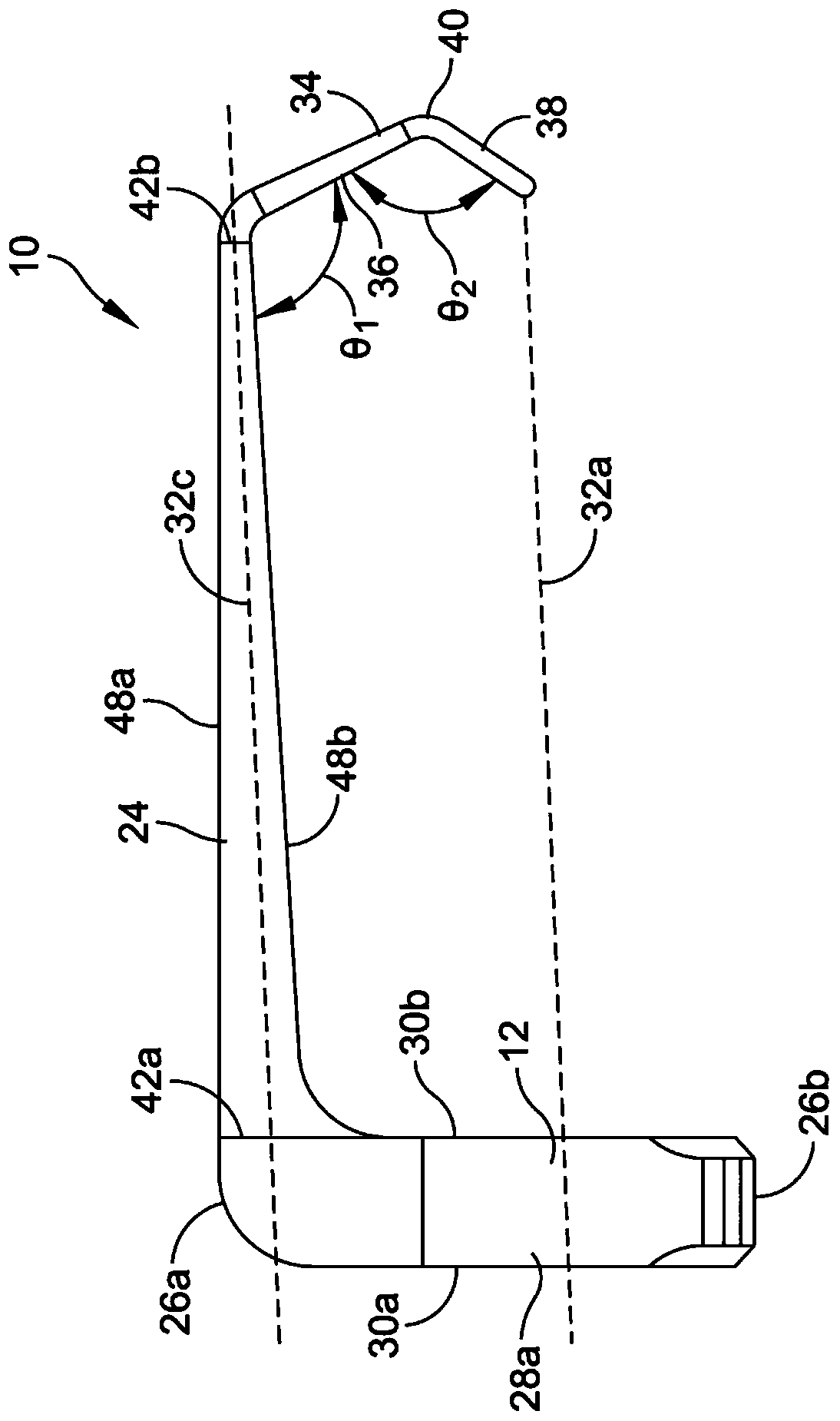
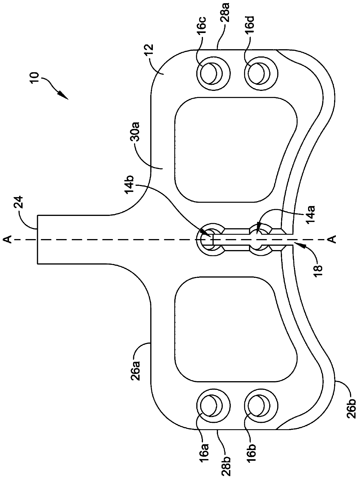
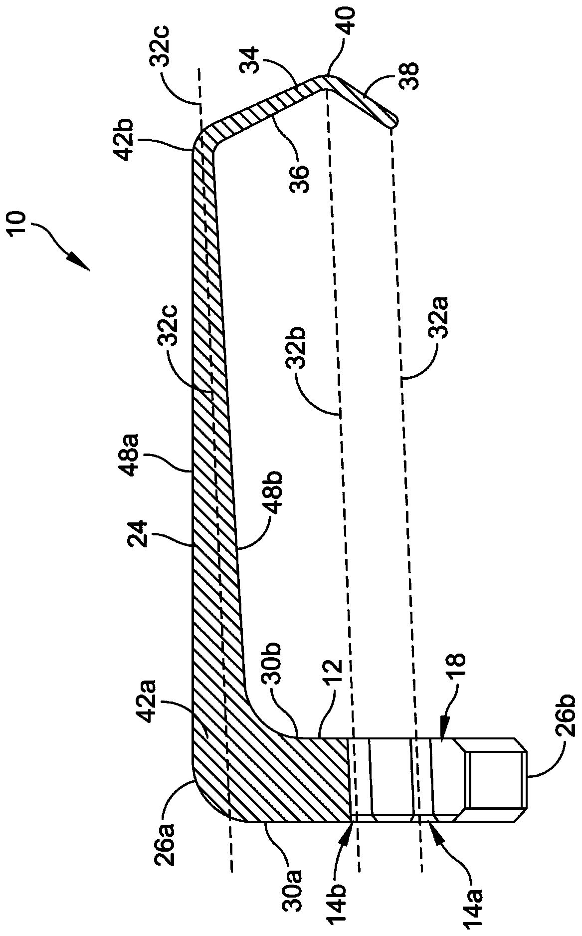
A targeting guide includes a body defining a first guide hole sized and configured to receive a guide sleeve therethrough. The first guide hole extends through the body on a first axis. An alignment arm extends between a first end and a second end. The first end is coupled to the body. A tip extends from the second end of the alignment arm. A free end of the tip is aligned with the first axis of the first guide hole.

Description

[0001] Cross References to Related Applications [0002] This application claims the benefit of U.S. Provisional Application Serial No. 62 / 541,410, filed August 4, 2017, entitled "SCREW TARGETING GUIDE SYSTEM ANDMETHOD," which is hereby incorporated by reference in its entirety. Background technique [0003] During surgery, such as foot surgery, it may be desirable to fix the position of the first and second bone segments. For example, in some cases, an osteotomy is made in the bone to correct one or more defects. After the osteotomy is formed, the first segment of bone and the second segment of bone are positioned to correct the defect and secured in place with one or more fixation elements. In other embodiments, one or more bone fragments are formed as a result of an injury and / or a medical procedure. [0004] Current systems rely on the placement of a guide element prior to insertion of the fixation element. Placement of the guide element is performed by the surgeon and ...

Claims


Application Information

Patent Timeline
Patent Type & Authority Applications(China)
IPC IPC(8): A61B17/88A61B17/86
CPCA61B17/1764A61B17/863A61B2017/565A61B17/1775A61B17/1778A61B17/1782A61B17/1725
Inventor 约瑟夫·瑞安·伍达德布莱恩·罗伯特·索伦保罗·卢特雷尔乔尔·韦诺斯大卫·雷德芬
Owner WRIGHT MEDICAL TECH
Learn More