Automobile part maintenance pressing and fixing device and pressing method thereof

A fixing device and pressing technology, applied in the field of auto parts maintenance, can solve the problems of lack of fine-tuning function, convenient application and operation process, etc., and achieve the effect of ensuring maintenance efficiency, convenient height adjustment, and easy handling and transfer.

Active Publication Date: 2019-12-06
湖南容光汽车部件有限公司
View PDF9 Cites 3 Cited by
  • Summary
  • Abstract
  • Description
  • Claims
  • Application Information

AI Technical Summary

Problems solved by technology

[0004] However, the existing automatic fastening device lacks the fine-tuning function, so that once the position deviates after the fastening and clamping, the material can only be cut again, and the second or even third clamping can be performed to ensure the position adjustment of the workpiece. The process is not more convenient than manual clamping

Method used


Image

  • Automobile part maintenance pressing and fixing device and pressing method thereof
  • Automobile part maintenance pressing and fixing device and pressing method thereof
  • Automobile part maintenance pressing and fixing device and pressing method thereof

Examples


Embodiment 1

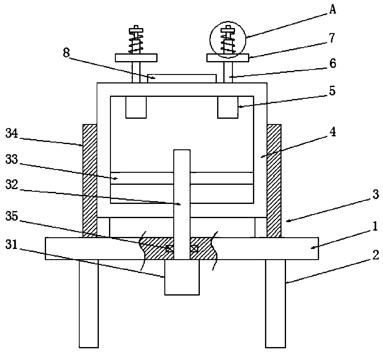
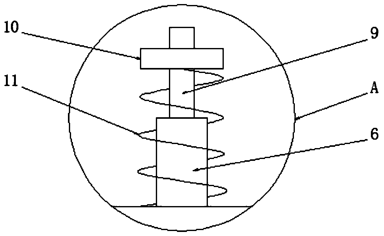
[0032] See Figure 1-2, a pressing and fixing device for repairing auto parts, comprising a bottom plate 1, a plurality of legs 2 are uniformly arranged on the bottom end of the bottom plate 1, and a lifting mechanism 3 is arranged on the top end of the bottom plate 1, and a lifting mechanism 3 is installed on the lifting mechanism 3. Lifting frame 4, described lifting frame 4 is a rectangular frame structure, workbench 8 is fixedly installed in the top middle part of lifting frame 4, and electric telescopic device 5 is installed symmetrically on the inner cavity top wall of lifting frame 4, and described electric telescopic device 5 The top of the telescopic rod 6 on the top runs through the top wall of the lifting frame 4 and is fixedly connected with a fine-tuning screw 9. The outer side of the telescopic rod 6 is provided with a pressing plate 7 matched with the workbench 8. Between the telescopic rod 6 and the pressing plate 7 It is a sliding connection, the fine-tuning s...

Embodiment 2

[0034] See figure 1 The difference from Embodiment 1 is that the lifting mechanism 3 includes a lifting motor 31 and two guide grooves 34 that match the lifting frame 4, the guide grooves 34 are U-shaped structures, and the two guide grooves 34 are slidably connected On the left and right sides of the lifting frame 4, the guide groove 34 is fixedly mounted on the base plate 1, and the lifting motor 31 is fixedly mounted on the bottom end of the base plate 1, and the lifting motor 31 is rotatably connected with a lifting screw rod 32, and the lifting screw rod 32 The top end passes through the bottom plate 1 and is screwed on the lifting frame 4. By rotating the lifting motor 31 in the forward direction, the lifting screw 32 is driven to rotate forward, and the lifting screw 32 is used to push the lifting frame 4 up along the guide groove 34, thereby adjusting the workbench upwards. At the same time, reversely rotate the lifting motor 31, thereby driving the lifting screw 32 to...

Embodiment 3

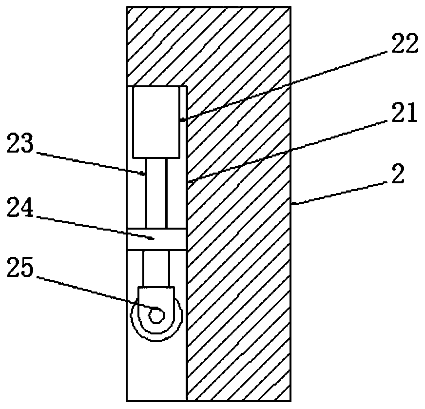
[0037] See image 3 , the difference from Embodiment 1 is that: one end of the leg 2 is provided with a storage chamber 21, and a hydraulic cylinder 22 is fixedly installed on the inner cavity top wall of the storage chamber 21, and the hydraulic rod 23 on the hydraulic cylinder 22 The bottom end of the bottom of the stable plate 24 is fixedly connected with the stable plate 24 matched with the storage chamber 21, and the stable plate 24 is slidingly connected with the storage cavity 21, and the bottom end of the stable plate 24 is fixedly equipped with a universal wheel 25. The universal wheel 25 is a universal self-locking wheel. When the whole device needs to be transferred, the hydraulic rod 23 is extended through the hydraulic cylinder 22, and the hydraulic rod 23 pushes the stabilizing plate 24 to slide down along the storage cavity 21, thereby lowering the universal wheel. 25. Utilize universal wheels 25 to support the entire device, so that the mobility of the entire d...


PUM


Abstract

The invention discloses an automobile part maintenance pressing and fixing device and a pressing method thereof. The automobile part maintenance pressing and fixing device comprises a base plate. A lifting mechanism is arranged at the top end of the base plate. A lifting frame is mounted on the lifting mechanism. A working platform is fixedly mounted in the middle of the top end of the lifting frame. The top wall of an inner cavity of the lifting frame is symmetrically provided with electric telescopic devices. Telescopic rods of the electric telescopic devices penetrate through the top wall of the lifting frame to be fixedly connected with fine adjustment screw rods. The outer side of each telescopic rod is sleeved with a pressing plate matched with the working platform. Each fine adjustment screw rod is sleeved with a fine adjustment nut in a threaded connection mode. The outer side of each fine adjustment screw rod is sleeved with a preload spring matched with the corresponding pressing plate. According to the automobile part maintenance pressing and fixing device, a workpiece is placed on the working platform; the telescopic rods of the electric telescopic devices are retractedto descend the pressing plates, and the pressing plates are pressed down to fasten the workpiece; and finally, the fine adjustment screw rods are rotated to squeeze or release the preload springs toconduct local repressing or local releasing of the pressing plates, and accordingly, the position of the workpiece is finely adjusted to ensure the pressing quality.

Description

technical field [0001] The invention relates to the technical field of auto parts maintenance, in particular to a compression fixing device and a compression method for auto parts maintenance. Background technique [0002] In recent years, with the continuous advancement of industrial technology and the continuous improvement of the economic level, automobiles, as a traditional luxury, have entered ordinary households, making automobiles gradually become ordinary commodities from luxury goods. Auto parts are the various units that make up the whole car and a product that serves the car. There are many kinds of auto parts. With the improvement of people's living standards, people consume more and more cars, and the market for auto parts is getting bigger and bigger. In recent years, auto parts manufacturers are also developing rapidly. [0003] In the process of car repair, we need to disassemble the car parts before repairing. In order to prevent the spare parts from loos...

Claims


Application Information

Patent Timeline
Patent Type & Authority Applications(China)
IPC IPC(8): B25B11/00B25H1/08B25H1/16B25H1/00
CPCB25B11/00B25H1/00B25H1/0007B25H1/08B25H1/16
Inventor 张娟娟张军玲周军奎
Owner 湖南容光汽车部件有限公司
Why Eureka
Try Eureka