
Reveiving portion of radio communicaition device

A technology of receiving part and equipment, applied in the direction of wireless communication, radio/induction link selection arrangement, communication between multiple stations, etc., can solve problems such as difficulty in changing the processing timing of received signals

Inactive Publication Date: 2003-04-09
PANASONIC CORP
View PDF2 Cites 0 Cited by
  • Summary
  • Abstract
  • Description
  • Claims
  • Application Information

AI Technical Summary

Problems solved by technology

Thus, it is difficult to change the timing of restarting the received signal processing by units shorter than the sleep cycle

Method used


Image

  • Reveiving portion of radio communicaition device
  • Reveiving portion of radio communicaition device
  • Reveiving portion of radio communicaition device

Examples


no. 1 Embodiment

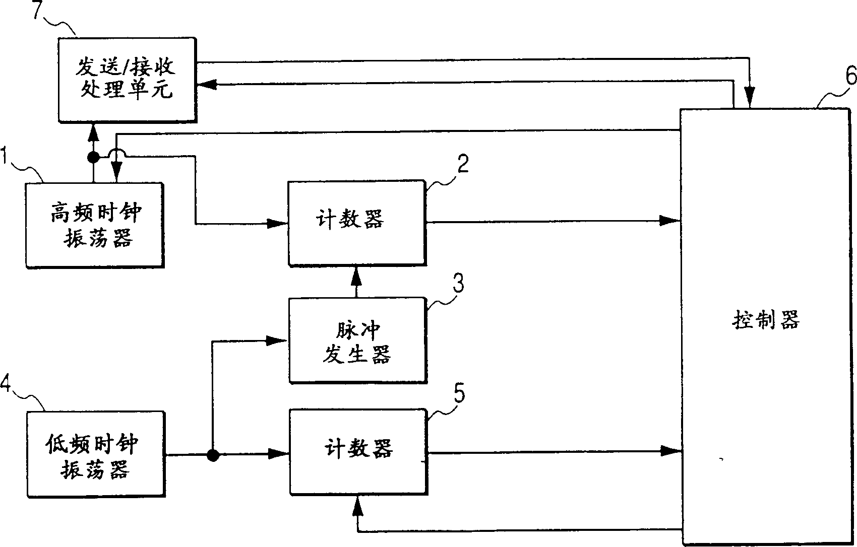
[0041] refer to figure 2 , The radio communication device of the first embodiment of the present invention includes: a high frequency clock oscillator 1, a counter 2, a pulse generator 3, a low frequency clock oscillator 4, a counter 5, a controller 6 and a sending / receiving processing unit 7. E.g, figure 2 A radio communication device is equivalent to a mobile station in a radio communication network.

[0042] The high-frequency clock oscillator 1 is connected to the counter 2 , the controller 6 and the sending / receiving processing unit 7 . Counter 2 is connected to pulse generator 3 and controller 6 . The pulse generator 3 is connected to a low frequency clock oscillator 4 . A low frequency clock oscillator 4 is connected to a counter 5 . The counter 5 is connected to a controller 6 . The controller 6 is connected to a transmission / reception processing unit 7 .

[0043] The high-frequency clock oscillator 1 generates a high-frequency clock signal having a frequency o...

no. 2 Embodiment

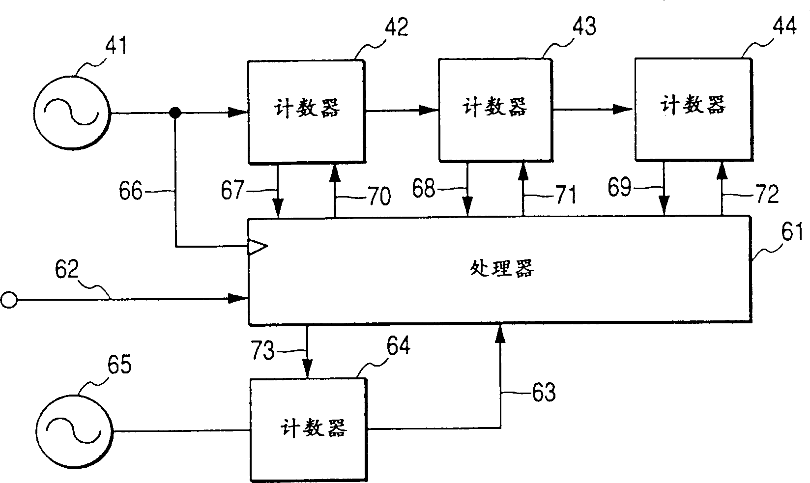
[0065] Figure 5 Represents the second embodiment of the present invention, except for the following design changes, others are the same as figure 2 The embodiment is the same. Figure 5 The embodiment includes a controller 6A and a transmit / receive processing unit 7A, instead of figure 2 The controller 6 and the sending / receiving processing unit 7. exist Figure 5 In the embodiment, the counter 5 is connected to the transmission / reception processing unit 7A. In this embodiment, the counter 5 periodically outputs a restart signal to the controller 6A and the transmission / reception processing unit 7A.

[0066] The transmission / reception processing unit 7A is designed for CDMA (Code Division Multiple Access). The transmission / reception processing unit 7A restarts its operation in response to the restart signal fed from the counter 5 .

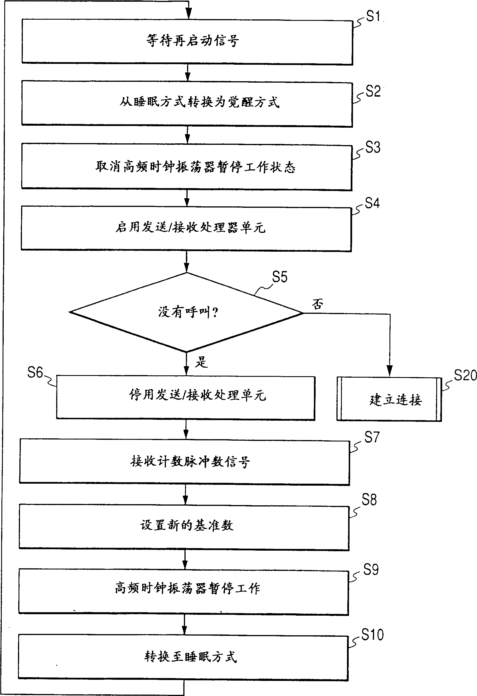
[0067] The controller 6A operates according to programs stored in its internal ROM. Image 6 is a flow chart of the program segments re...


PUM


Abstract

A receiving portion of a radio communication device includes a circuit periodically moving into a sleep mode of operation. The circuit periodically moves out of the sleep mode of operation in response to a re-activation signal. A first clock signal is generated and is counted. The re-activation signal is generated each time the number of the counted clock pulses in the first clock signal reaches an updatable number. A second clock signal is generated which has a frequency higher than a frequency of the first clock signal and is counted during every time interval determined by the first clock signal. An error of the frequency of the first clock signal with respect to the frequency of the second clock signal is calculated on the basis of a result of the counting to set an updatable number. The invention has a merit for reliably implementing RAKE reception.

Description

technical field [0001] The present invention relates to a receiving part of a radio communication device such as a mobile telephone. Background technique [0002] Some mobile phones have a receiving section that periodically goes into a sleep mode of operation. When the receiving part is in sleep mode, most circuits of the receiving part do not work to save power. At the expected timing when the base station transmits the polling signal, the receiving section switches from the sleep operation mode to an awake mode (normal mode or standby mode). [0003] British Patent Application GB2297884A corresponding to Japanese Patent Application Laid-Open No. Hei 8-251656 discloses a power saving device in a mobile phone. In this application, the mobile phone has a high frequency system clock and a processor which processes polling signals received when the phone is in standby. The phone can be put to sleep by deactivating the system clock when no polling signal is received. A rest...

Claims


Application Information

Patent Timeline
IPC IPC(8): G06F1/04H04B1/16H04B7/26H04M1/73H04W52/02
CPCH04W52/0283H04W52/029H04B2201/70709H03L7/00H03L1/00Y02D30/70H03L7/0814
Inventor 浅野延夫
Owner PANASONIC CORP
Learn More