
Thread clamping device

A technology of thread clamp and trigger lever, which is applied in the field of thread clamp, and can solve problems such as muscle damage, hand burden, and labor-consuming

Active Publication Date: 2019-12-10
XPIDER
View PDF6 Cites 0 Cited by
  • Summary
  • Abstract
  • Description
  • Claims
  • Application Information

AI Technical Summary

Problems solved by technology

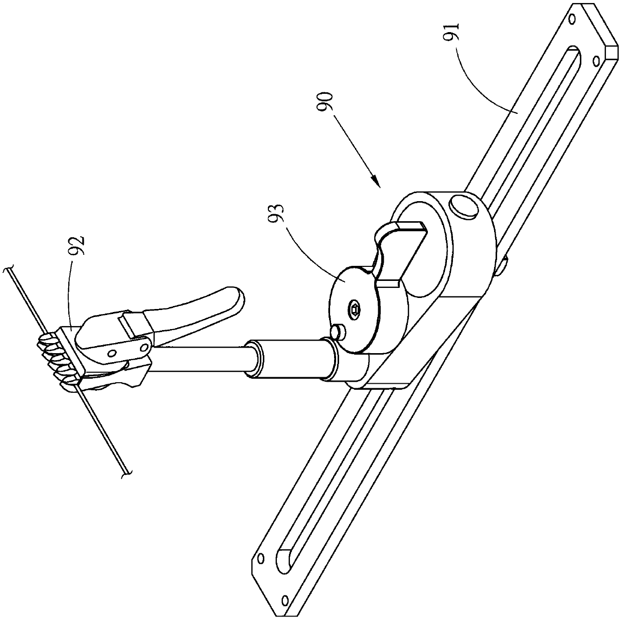
[0004] However, during operation, the clamping member 92 is usually clamped on the racket line to fix the clamping position, and then the clamping member 92 is released to rotate the knob 93 to fix the clamping device 90. The clamp 90 has not yet been forced, and when the clamp 92 is released, it is easy to change the position of the clamp 90 due to accidental touch, resulting in the need to readjust the clamping position; The user usually turns the knob 93 hard with the index finger and thumb; because the thread clamp 90 needs to be fixed and loosened many times in the process of threading, so long-term use is harmful to the user's hands. Easy to cause burden and muscle damage
Furthermore, if the applied force is too large when the knob 93 is turned, the cam or the screw that the knob 93 cooperates with is relatively too tight on the track 91, and it will take more effort and time to loosen the knob 93, resulting in a reduction in threading efficiency.

Method used


Image

  • Thread clamping device
  • Thread clamping device
  • Thread clamping device

Examples


Embodiment Construction

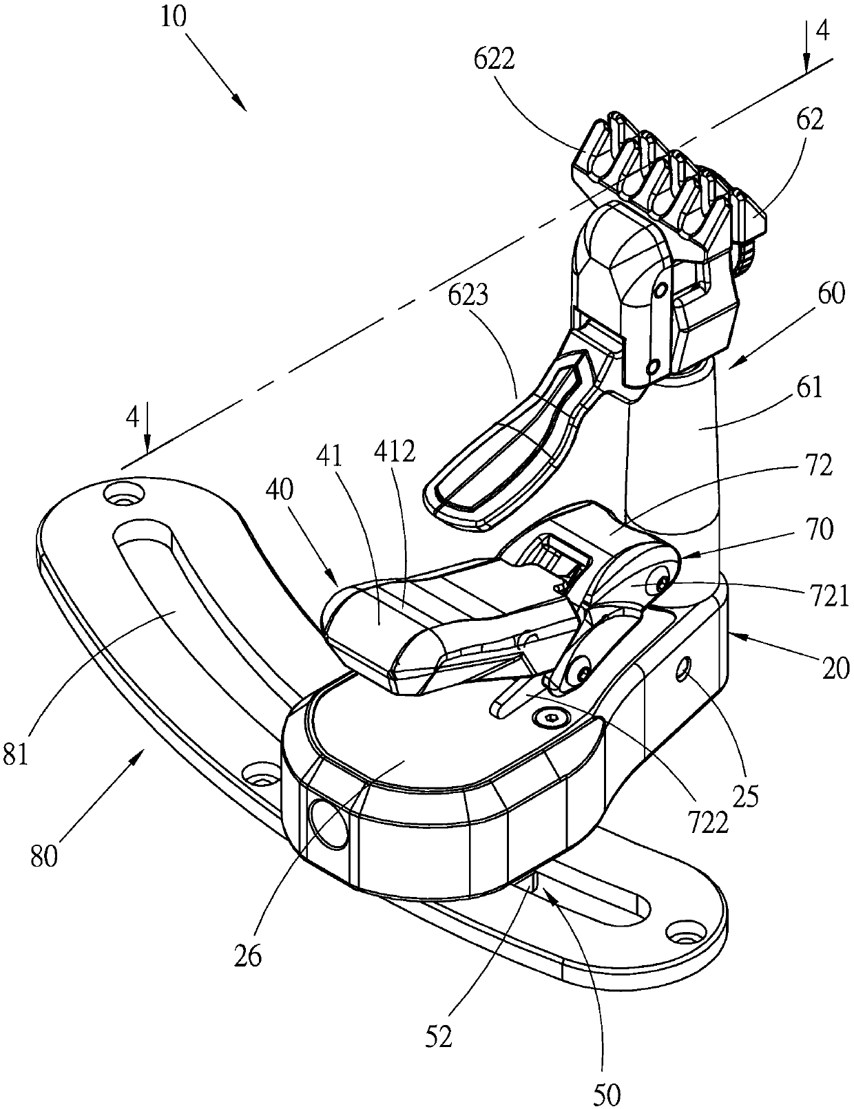
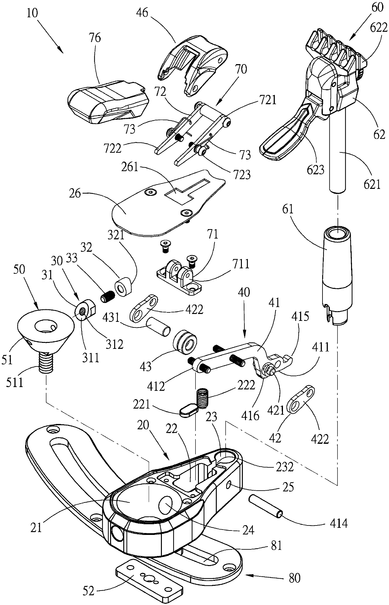
[0033] see Figure 2 to Figure 4 , the thread gripper 10 of the racket threader of a preferred embodiment of the present invention includes:

[0034] The seat body 20 is provided with a space, a channel 22 and a container groove 23 in sequence from one end to the other end. In this preferred embodiment, the space is a tapered hole 21 that is wide at the top and narrow at the bottom, which at least runs through the seat body 20 bottom surface; the channel 22 communicates with the tapered hole 21 with a connecting hole 24, and the channel 22 is provided with a pivot hole 25 close to the side of the tank 23, and the axis direction of the pivot hole 25 and the connecting hole 24 is approximately perpendicular ; The bottom of the channel 22 is provided with a pad 221 and an elastic element 222, the pad 221 is made of a material with low friction, and its top surface is flat; the elastic element 222 is a compression spring; the container 23 It communicates with the channel 22 with ...


PUM


Abstract

The invention provides a thread clamping device. The thread clamping device includes a seat body, a transmission member, a wrench mechanism, a tightening mechanism and a thread clamping mechanism; theseat body is provided with a space and a channel, and the space and the channel communicate with each other through a connection hole; the transmission member arranged in the connection hole in a penetrating manner; the wrench mechanism includes a wrench lever and a connecting rod; the connecting rod is pivotally arranged to the wrench lever and located in the channel, and the free end of the connecting rod faces the transmission member; the tightening mechanism is accommodated in the space by an actuating block, and the actuating block is connected with a clamping block; the thread clampingmechanism is arranged on the seat body; and a thread clamping member is arranged on the top of the thread clamping mechanism for clamping a racket thread. When the wrench mechanism is pressed down sothat the force of the wrench lever and the connecting rod and the force of the wrench lever and the transmission member are on the same straight line, the transmission member can support the tightening mechanism to form a restraint; the downward force is in accordance with the human engineering; and the force of pressing each time is fixed, so that excessive tightness cannot be caused.

Description

technical field [0001] The present invention relates to a racket threader, in detail, it refers to a thread gripper which is easy to operate and has stable pressing force. Background technique [0002] With the prosperity of badminton and tennis, users have relatively higher requirements for the rackets they use, and the situation that the racket strings are threaded on the surface of the racket becomes more important. For known racquet stringers, see figure 1 As shown, after a racket string passes through the racket frame, a string clamp 90 will be used to clamp and fix the racket string. The string clamp 90 can be moved and fixed on a track 91 of the racket stringing machine. The thread clamp 90 clamps the racket string that is tightened to a predetermined number of pounds with a thread clamp 92, then loosens the clamp 92 that clamps the racket string, and then moves the thread clamp 90 to the next one to be clamped. The position of the racket string. [0003] The threa...

Claims


Application Information

Patent Timeline
Patent Type & Authority Applications(China)
IPC IPC(8): A63B51/14
CPCA63B51/14
Inventor 林家永
Owner XPIDER
Learn More