Unmanned aerial vehicle

A technology of drones and receivers, applied in the field of drones, can solve problems such as signal transmission delay

Inactive Publication Date: 2019-12-10
FLYSKY TECH CO LTD
View PDF7 Cites 1 Cited by
  • Summary
  • Abstract
  • Description
  • Claims
  • Application Information

AI Technical Summary

Problems solved by technology

[0003] The present invention solves the problem of signal transmission delay; at the same time, the present invention also provides a

Method used


Image

  • Unmanned aerial vehicle
  • Unmanned aerial vehicle
  • Unmanned aerial vehicle

Examples


Embodiment Construction

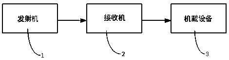
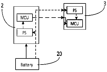
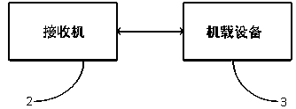
[0019] In order to make the object, technical solution and advantages of the present invention clearer, the present invention will be further described in detail below in conjunction with the accompanying drawings and embodiments. It should be understood that the specific embodiments described here are only used to explain the present invention, not to limit the present invention. In the description of the present invention, it should be noted that the terms "center", "upper", "lower", "left", "right", "vertical", "horizontal", "inner", "outer" etc. The indicated orientation or positional relationship is based on the orientation or positional relationship shown in the drawings, and is only for the convenience of describing the present invention and simplifying the description, rather than indicating or implying that the referred device or element must have a specific orientation, or in a specific orientation. construction and operation, therefore, should not be construed as li...


PUM


Abstract

The invention provides an unmanned aerial vehicle. The unmanned aerial vehicle comprises a receiver and airborne equipment; the receiver is used for receiving analog control signals sent by a transmitter to convert the analog control signals into digital control signals to send to the airborne equipment, and the receiver sends the digital control signals to the airborne equipment, so that the problem of signal delay is solved; and the airborne equipment performs corresponding actions according to the digital control signals, and the airborne equipment performs corresponding actions after receiving the digital control signals.

Description

technical field [0001] The invention belongs to the field of wireless remote control, in particular to an unmanned aerial vehicle. Background technique [0002] Unmanned aircraft, unmanned vehicles, and unmanned ships in the model field are all controlled by wireless remote control. During the control process, the remote control sends the remote control commands collected by the transmitter to the receiver through wireless signals, and the receiver will The received control commands are converted into industry-standard PWM drive signals to drive airborne equipment such as ESCs and steering gears. However, the frequency of the traditional PWM driving signal is between 50HZ and 400HZ, and the signal response delay can exceed 20ms at most, and it can only be controlled in one direction, and cannot feedback the working status of the device in a closed loop. At the same time, each output channel of the traditional receiver can only output one channel drive signal. Contents of ...

Claims


Application Information

Patent Timeline
IPC IPC(8): B64C39/02G08C17/02
CPCB64C39/024G08C17/02B64U2201/20
Inventor 杨坤林厉翔龙
Owner FLYSKY TECH CO LTD
Why Eureka
Try Eureka